

Japan Patent Office publishes case examples of "Examination Guidelines for Patent and Utility Model" for IoT related technology.
The details are as follows.
Case examples of "Examination Guidelines for Patent and Utility Model" for IoT related technology
1. Cases pertinent to Eligibility for Patent
[Case 3-2] Sugar Content Data of Apples and a Method for Predicting Sugar Content Data of Apples
Title of Invention
Sugar Content Data of Apples and a Method for Predicting Sugar Content Data of Apples
What is claimed is:
[Claim 1]
Sugar content data of preharvest apples on trees measured by a portable sugar content sensor for apples which performs reflective near-infrared spectroscopic analyses.
(Claim 1: Does not fall under "invention.")
[Claim 2]
The sugar content data of apples as described in Claim 1 received by a receiving unit of a server and stored in a memory unit of the said server.
(Claim 2: Does not fall under "invention.")
[Claim 3]
A method for predicting sugar content data of apples comprising;
a step in which an analyzing unit of the server analyzes the relationship between sugar content data of preharvest apples for specified periods and data on meteorological conditions, and sugar content data of apples at the time of their shipping, based on past performance;
a step in which the receiving unit of the said server receives the sugar content data of apples for specified periods as described in Claim 1; and
a step in which a prediction unit of the said server predicts and outputs sugar content data of apples at the time of future shipping using the said received sugar content data of apples for specified periods and data on past and future meteorological conditions as inputs, based on the said analyzed relationships.
(Claim 3: Falls under "invention." )
[Technical Field] The present invention relates to sugar content data of apples and a method for predicting sugar content data of apples.
[Background Art] The sugar content of apples is an important indicator at the time of shipping apples. Therefore, the sugar content of apples has been measured at the time of shipping. Apples are shipped after being graded based on measured sugar content and other conditions and the apple farmers change cultivation conditions of the following year as needed.
On the other hand, if sugar content data of preharvest apples on trees can be measured, it becomes possible to provide support for cultivation by predicting sugar content data of apples at the time of their shipping to push the sugar content of those apples closer to a desired level during their cultivation.
[Problems to be solved by the invention] The present invention was created taking such circumstances into consideration and aims to provide support for cultivation based on the data to push the sugar content of those apples closer to a desired level by measuring sugar content data of preharvest apples on trees and by predicting sugar content data of apples at the time of their shipping.
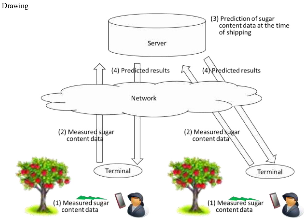
[Solution for the Problem to be solved] In the present invention sugar content data of preharvest apples on trees is measured with a portable sugar content sensor for apples. The said sugar content sensor for apples measures a sugar content of those apples by irradiating near-infrared lights on apples and performing spectroscopic analyses of reflected lights. Although this principle of measurement is the same as the conventional measurement of sugar content of apples performed at the time of their shipping, in the present invention sugar content data of preharvest apples on trees is measured since a portable sugar content sensor for apples has been developed in response to the progress of sensor technology. The said sugar content sensor for apples is equipped with the communication function and can transmit measured sugar content data to the server directly or via a terminal of an apple farmer.
This sugar content data of apples is used for analysis and prediction by the server.
The server makes analyses through the following steps (1) - (4).
(1) A step in which a receiving unit of the server receives during a specified period daily sugar content data of preharvest apples on trees from terminals of a plurality of apple farmers via the network.
(2) A step in which the receiving unit of the server receives data on meteorological conditions for specified periods before apples are harvested and sugar content data of apples at the time of their shipping. Meteorological conditions are selected arbitrarily from the amount of sunlight, temperature, the amount of rainfall, humidity, etc. Meteorological conditions may be those at a place where apples are cultivated or at a point or an area where the server is installed. If the place where apples are cultivated and the point where the server is installed are not so far as to cause differences in meteorological conditions, those at the point or area where the server is installed may be adopted. Moreover, sugar content data of apples at the time of their shipping is measured for grading as in the past.
(3) A step in which a memory unit of the server stores the received sugar content data of apples for specified periods and data on meteorological conditions, and the sugar content data of apples at the time of their shipping as one combination. The server accumulates a sufficient amount of data on the said combination as actual values in order to obtain adequate results of the analyses explained in (4).
(4) A step in which an analyzing unit of the server analyzes, based on the said data stored in the memory unit, the relationship between sugar content data of apples for specified periods before they are harvested and data on meteorological conditions, and sugar content data of apples at the time of their shipping by means of machine learning. An arbitrary technique such as deep learning of neural networks is used for this machine learning. For example, neural networks are configured in a way that sugar content data of apples measured prior to a point X days before their harvest and data on meteorological conditions before their harvest are input in the input layer and sugar content data of apples at the time of their shipping is output from the output layer. Weights between neurons of the neural networks are optimized by means of supervised learning using analytical data obtained by tagging the input dada in the input layer and the output data from the output layer.
Then, a prediction by the server is made through the following steps (5) - (8).
(5) A step in which the receiving unit of the server receives sugar content data of preharvest apples on trees for specified periods from terminals of apple farmers via the network.
(6) A step in which the receiving unit of the server receives data on past meteorological conditions to date and data on predicted meteorological conditions for the future from the present to the date of shipping. Meteorological conditions are selected arbitrarily from the amount of sunlight, temperature, the amount of rainfall, humidity, etc. in the same manner as (2) above. However, the receiving unit receives predicted future meteorological conditions in this process for the purpose of making a prediction described later.
(7) A step in which the memory unit of the server stores the received data.
(8) A step in which a prediction unit of the server, based on the relationships obtained by performing the analyses described in the process (4), predicts sugar content data of apples at the time of future shipping using data stored therein by inputting the data on measured sugar content of apples for specified periods and the data on past and future meteorological conditions. In the case of the neural networks mentioned in (4), a prediction is made by inputting sugar content data of apples measured prior to the point of X days before the harvest and data on meteorological conditions prior to the point of X days before the harvest as well as data on meteorological conditions after the said point of X days before the harvest in the input layer and by outputting sugar content data of apples at the time of their shipping from the output layer.
Then, the server transmits predicted sugar content data of apples at the time of their shipping to terminals of apple farmers via the network. The apple farmers examine if they need to change cultivation conditions, etc. based on the predicted sugar content data of apples at the time of their shipping.
[Effect of Invention] The present invention can provide support for cultivation based on the data to push the sugar content of those apples closer to a desired level by measuring sugar content data of preharvest apples on trees and by predicting sugar content data of apples at the time of their shipping.
[Conclusion] The invention of Claim 1 does not fall under "invention."
The invention of Claim 2 does not fall under "invention."
The invention of Claim 3 falls under "invention."
[Explanation]
- Claim 1
Mere presentation of information (where the feature resides solely in the content of the information, and the main object is to present information), such as presentation of information (presentation per se, means for presentation or method of presentation) in which a technical feature does not reside, does not fall under "invention" ("creation of the technical idea utilizing a law of nature") mentioned in the main paragraph of Article 29(1).
Since Claim 1 does not specify any means for or a method of presenting sugar content data of apples, the sugar content data of apples of Claim 1 is considered to be characterized only in the content of information that “sugar content data of preharvest apples on trees measured by a portable sugar content sensor for apples which performs reflective near-infrared spectroscopic analyses”. Therefore, the sugar content data of apples of Claim 1 does not have technical features in the presentation of information (presentation per se, means for presentation or method of presentation), its feature resides solely in the content of the information, and its main object is to present information.
Therefore, since the sugar content data of apples of Claim 1 is mere presentation of information, it is not a creation of the technical idea utilizing a law of nature and thus does not fall under “invention”.
- Claim 2
Although Claim 2 identifies the sugar content data of apples of Claim 1 as “received by a receiving unit of a server and stored in a memory unit of the server”, it does not specify any means for or method of presenting the sugar content data of apples. Therefore, it is still considered that its feature resides solely in the content of information. Therefore, the sugar content data of apples of Claim 2 does not have technical features in the presentation of information (presentation per se, means for presentation or method of presentation), its feature resides solely in the content of the information, and its main object is to present information.
Therefore, since the sugar content data of apples of Claim 2 is mere presentation of information, it is not a creation of the technical idea utilizing a law of nature and thus does not fall under “invention”.
- Claim 3
The invention of Claim 3 is a method for predicting sugar content data of apples using the computer software. The method for predicting sugar content data of apples comprises “a step in which an analyzing unit of the server analyzes the relationship between sugar content data of preharvest apples for specified periods and data on meteorological conditions, and sugar content data of apples at the time of their shipping, based on past performance; a step in which the receiving unit of the said server receives the sugar content data of apples for specified periods as described in Claim 1 (sugar content data of preharvest apples on trees measured by a portable sugar content sensor for apples which performs reflective near-infrared spectroscopic analyses); and a step in which a prediction unit of the said server predicts and outputs sugar content data of apples at the time of future shipping using the said received sugar content data of apples for specified periods and data on past and future meteorological conditions as inputs, based on the said analyzed relationships”. Therefore, the invention of Claim 3 is what concretely performs information processing based on the technical properties such as chemical or biological properties of apples.
Therefore, the invention of Claim 3 is a creation of the technical idea utilizing a law of nature as a whole and thus falls under “invention”.
(Supplementary explanation)
Since the determination whether or not the inventions of Claim 3 fall under “inventions” is judged in accordance with “Examination Guidelines Part III, Chapter 1: Eligibility of Invention and Industrial Applicability”, and thus is not examined from a viewpoint of the computer software.
[Measures of the applicant] It is understood that regarding the sugar content data of apples its feature resides solely in the content of the information as far as the description etc. are referred to. Therefore, the sugar content data of apples of Claim 1 and 2 cannot overcome the reason for refusal.
[Case 3-3] 3D printing data of dolls and a 3D printing method of dolls
Title of Invention
3D printing data of dolls and a 3D printing method of dolls
What is claimed is:
[Claim 1] 3D printing data of dolls read in a control unit of a 3D printer when a modeling unit of the said 3D printer models, characterized in that it includes three-dimensional shapes and color tones of dolls to be modeled.
(Claim 1: Does not fall under "invention.")
[Claim 2] A 3D printing method of dolls using the said 3D printer based on the 3D printing data of dolls as described in Claim 1, comprising;
a step in which the said control unit reads in the said 3D printing data;
a step in which the said control unit controls the said modeling unit in a way that it dispenses modeling resin based on the three-dimensional shape included in the said 3D printing data; and
a step in which the said control unit controls the said modeling unit in a way that it dispenses colorants of a plurality of colors based on the color tones included in the 3D printing data.
(Claim 2: Falls under "invention.")
Overview of the description
[Technical Field] The present invention relates to 3D printing data of dolls and a 3D printing method of dolls.
[Background Art] In general, dolls made of synthetic resin are produced by means of mold injection. However, dolls are produced in small quantities and large varieties so that a number of molds are required to produce these products by means of mold injection. Thus, production costs of dolls increase.
[Problems to be solved by the invention] The present invention was realized in view of these circumstances and aims to provide dolls to the society at reasonable cost.
[Solution for the Problem to be solved] (Omitted)
[Effect of Invention] 3D printing data of dolls of the present invention includes three-dimensional shapes and color tones of dolls to be modeled. Dolls can be easily produced by means of a 3D printer and they do not require molds for mold injection. Therefore, dolls will be provided to the society at reasonable cost.
[Conclusion] The invention of Claim 1 does not fall under "invention."
The invention of Claim 2 falls under “invention.”
[Explanation]
- Claim 1
Mere presentation of information (where the feature resides solely in the content of the information, and the main object is to present information), such as presentation of information (presentation per se, means for presentation or method of presentation) in which a technical feature does not reside, does not fall under "invention" ("creation of the technical idea utilizing a law of nature") mentioned in the main paragraph of Article 29(1).
It is an ordinary operation of a 3D printer that the 3D printing data is “read in a control unit of a 3D printer when a modeling unit of the said 3D printer models” as described in Claim 1. The 3D printing data of dolls of Claim 1 does not add any technical feature to the means for or method of reading data in the control unit of the 3D printer, but it is characterized only in the content of information that “it includes three-dimensional shapes and color tones of dolls to be modeled”. Therefore, the 3D printing data of Claim 1 does not have technical features in the presentation of information (presentation per se, means for presentation or method of presentation), its feature resides solely in the content of the information, and its main object is to present information.
Therefore, since the 3D printing data of dolls of Claim 1 is mere presentation of information, it is not a creation of the technical idea utilizing a law of nature and thus does not fall under “invention”.
- Claim 2
The invention of Claim 2 is a 3D printing method of dolls by a 3D printer using the computer software. The 3D printer controls a modeling unit in a way that it dispenses modeling resin and colorants of a plurality of colors based on three-dimensional shapes and color tones included in the 3D printing data. Therefore, the invention of Claim 2 is what concretely performs control of 3D printer which is an apparatus, or processing with respect to the control.
Therefore, since the invention of Claim 2 is a creation of the technical idea utilizing a law of nature as a whole, it falls under “invention”.
(Supplementary explanation)
Since the determination whether or not the invention of Claim 2 falls under “invention” is judged in accordance with “Examination Guidelines Part III, Chapter 1: Eligibility of Invention and Industrial Applicability”, and thus is not examined from a viewpoint of the computer software.
[Measures of the applicant] It is understood that regarding the 3D printing data of dolls its feature resides solely in the content of information as far as the detailed description of the invention etc. are referred to. Therefore, the 3D printing data of dolls of Claim 1 cannot overcome the reason for refusal.
(Reference)
For 3D printing data that falls under “invention”, see Case 2-15 in “Annex B, Chapter 1: Computer Software Related Inventions, 3. Case Examples”.
[Case 4-2] Operation Method and Operation Program for Electric Rice Cooker
Title of Invention
Operation Method and Operation Program for Electric Rice Cooker
What is claimed is:
[Claim 1] A method of operating an electric rice cooker communicative with an external server through a network, comprising:
a step of receiving information on users’ preferences of rice cooking, users’ home arrival time, and whether or not to eat at home the external server;
a step of setting the time of starting rice boiling so that the rice boiling is completed just before the earliest home arrival time of users who have plans to eat at home based on information on the arrival time and whether or not to eat at home; and
a step of performing the rice boiling in an optimum manner of rice cooking for users who have plans to eat at home based on information on users’ preferences of rice cooking and whether or not to eat at home.
[Claim 2] An operation program for causing an electric rice cooker to carry out the method described in Claim 1.
Overview of the description
The electric rice cooker, and the external server for managing information on users’ preferences of rice cooking and the schedule of a plurality of users who utilize the electric rice cooker are connected to each other through the network. The user can access the external server through the network using the user’s portable terminal, and the user can suitably register/update information on preferences of rice cooking and the schedule in the external server. The electric rice cooker can provide the following additional functions by utilizing information on users’ preferences of rice cooking, the home arrival time, and whether or not to eat at home, which is acquired from the external server.
(1) The time of starting rice boiling is set so that the rice boiling is completed just before the earliest home arrival time of the users who have plans to eat at home based on information on the users’ home arrival time and whether or not to eat at home.
(2) The rice boiling is performed in an optimum manner of rice cooking for preferences of rice cooking for users who have plans to eat at home based on information on users’ preferences of rice cooking and whether or not to eat at home. As for the users’ preferences of rice cooking, there are “soft and sticky feeling”, “crisp feeling”, and the like representing the texture of the cooked rice. Every users’ preferences are recorded in advance in the external server. As for the optimized manner of rice cooking, the rice boiling for which the boiling time, the temperature, and the like are appropriately controlled is conducted so as to satisfy the preferences of all the users who have plans to eat at home.
[Conclusion] The invention of Claim 1 falls under “invention”.
The invention of Claim 2 falls under “invention”.
[Explanation]
- Claim 1
The invention of Claim 1 is the method for operating the electric rice cooker utilizing the computer software. In addition, the electric rice cooker controls itself in the start time of the rice boiling and details of rice cooking based on information on users’ preferences of rice cooking, the home arrival time, and whether or not to eat at home acquired from the external server. Therefore, the invention of Claim 1 concretely performs the control for rice boiling of the electric rice cooker as the apparatus or the processing with respect to the control. Accordingly, the invention of Claim 1 is the creation of the technical idea utilizing the law of nature, and thus falls under “invention”.
- Claim 2
The invention of Claim 2 is the program for causing the computer to carry out the method that falls under “invention”. Therefore, the invention of Claim 2 is the creation of the technical idea utilizing the law of nature as a whole and falls under “invention”.
(Supplementary explanation)
Since the determination whether or not the inventions of clam 1 and 2 fall under “inventions” is judged in accordance with “Examination Guidelines Part III, Chapter 1: Eligibility of Invention and Industrial Applicability”, and thus is not examined from a viewpoint of the computer software.
[Case 2-9] Method of Allocating Unmanned Autonomous Vehicle 1
Title of Invention
Method of Allocating Unmanned Autonomous Vehicle 1
What is claimed is:
[Claim 1] A system of allocating unmanned autonomous vehicle comprising a vehicle allocation server, a portable terminal which a person who desires a vehicle allocation has, and unmanned autonomous vehicles,
wherein the portable terminal comprises:
a transmitting unit for transmitting the user ID and a vehicle allocation position to the vehicle allocation server,
wherein the vehicle allocation server comprises:
a storing unit for storing information on a face image of a user corresponding to a user ID;
an acquiring unit for acquiring information on the face image made to correspond to the user ID from the storing unit;
a specifying unit for specifying a unmanned autonomous vehicle which can be allocated based on position information and a utilization state of the unmanned autonomous vehicle; and
a transmitting unit for transmitting information on the vehicle allocation position and information on the face image to the specified unmanned autonomous vehicle, and
wherein the unmanned autonomous vehicle comprises:
an autonomous driving unit for performing autonomous driving up to the vehicle allocation position;
a face authentication unit for performing face authentication processing for surrounding people; and
a judging unit for judging a person having a face matching the received face as the person who desires vehicle allocation, thereby permitting utilization of the unmanned autonomous vehicle.
(Claim 1: Falls under "invention.")
[Claim 2] A method implemented in a system of allocating unmanned autonomous vehicle comprising a vehicle allocation server, a portable terminal which a person who desires a vehicle allocation has, and unmanned autonomous vehicles,
wherein the portable terminal comprises:
a step of transmitting the user ID and a vehicle allocation position to the vehicle allocation server,
wherein the vehicle allocation server comprises:
a step of storing information on a face image of a user corresponding to a user ID;
a step of acquiring information on the face image made to correspond to the user ID from the storing unit;
a step of specifying a unmanned autonomous vehicle which can be allocated based on position information and a utilization state of the unmanned autonomous vehicle; and
a step of transmitting information on the vehicle allocation position and information on the face image to the specified unmanned autonomous vehicle, and
wherein the unmanned autonomous vehicle comprises:
a step of performing autonomous driving up to the vehicle allocation position by an autonomous driving unit;
a step of performing face authentication processing for surrounding people by a face authentication unit; and
a step of judging a person having a face matching the received face as the person who desires vehicle allocation, thereby permitting utilization of the unmanned autonomous vehicle.
(Claim 2: Falls under "invention." )
Description
[Background Art] The present invention relates to a service utilizing unmanned autonomous vehicles within a predetermined site in an amusement park, a theme park or the like.
[Problems to be solved by the invention] As moving means within a predetermined site in an amusement park, a theme park or the like, there is a vehicle, such as a shuttle bus, traveling along a specific route but there was not a service for providing visitors with a vehicle which is freely moving within a large site like a taxi.
[Solution for the Problem to be solved] To solve the problem, the present invention provides a vehicle allocating service including authentication of users and utilizing known techniques of unmanned autonomous vehicles for which drivers are unnecessary and are capable of performing autonomous driving.
First, to provide a predetermined site with a plurality of unmanned autonomous vehicles as they can freely travel within the site. The user accesses the vehicle allocation server using his/her portable terminal in the site, thereby enabling the unmanned autonomous vehicle to travel to the desired vehicle allocation position. The vehicle allocation server which has received the vehicle allocation request specifies an unmanned autonomous vehicle which can be allocated, and issues an instruction for the specific unmanned autonomous vehicle to travel toward the vehicle allocation position. After having arrived at the vehicle allocation position through the autonomous driving, the unmanned autonomous vehicle performs the authentication of the user based on the face authentication, and urges the user to get on the unmanned autonomous vehicle as soon as the authentication is completed. Accordingly, the user can move to the desired destination within the site in a sense of using a taxi.
[Description of the embodiments] Hereinafter, a concrete system configuration and contents of operation will be described.
A plurality of unmanned autonomous vehicles, a vehicle allocation server, and a portable terminal within the predetermined site can communicate with each other through the network. The vehicle allocation server unitarily manages the position information of the unmanned autonomous vehicles and the current utilization states which indicate whether or not the user is getting on.
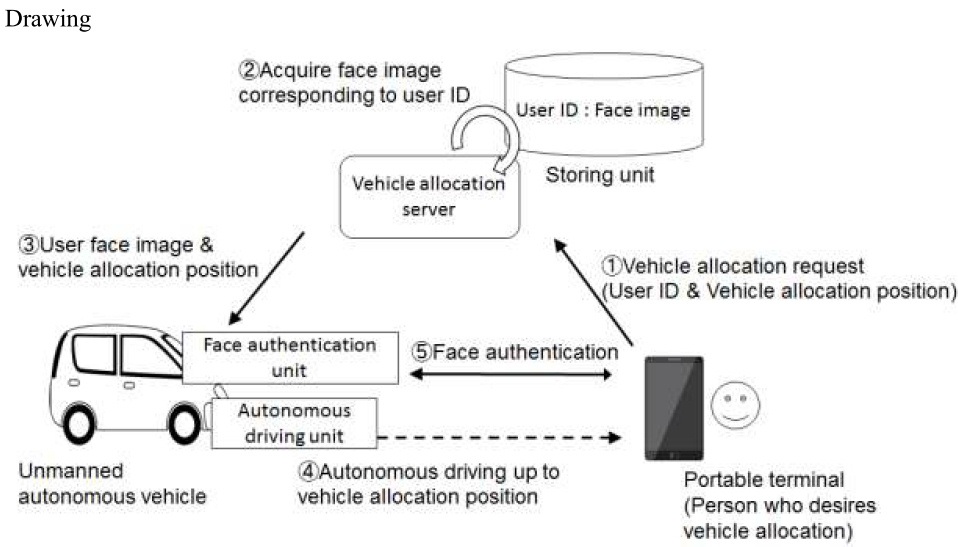
The user as the person who desires the vehicle to be allocated, firstly, manipulates his/her portable terminal, thereby requesting the vehicle allocation server to allocate the unmanned autonomous vehicle for which the vehicle allocation position is specified. Then, information including the user ID of the person who desires the vehicle allocation, and the vehicle allocation position is transmitted to the vehicle allocation server. The vehicle allocation server includes a storing unit in which face images of the users are previously made to correspond to the user IDs. Thus, when having received the user ID and the vehicle allocation position from the portable terminal, the vehicle allocation server acquires the face image made to correspond to the user ID from the storing unit. Subsequently, the vehicle allocation server specifies an unmanned autonomous vehicle which can be allocated based on the position information and the utilization states, of the unmanned autonomous vehicles, which are acquired through the network. Then, the vehicle allocation server transmits information on the vehicle allocation position and information on the face image to the specified unmanned autonomous vehicle, and issues an instruction to the specified unmanned autonomous vehicle to travel to the vehicle allocation position.
The unmanned autonomous vehicle equips an autonomous driving unit which is capable of performing autonomous driving for the destination even if a driver is absent. The unmanned autonomous unit is implemented by a known technique, which is, for example, processing various pieces of information such as the vehicle peripheral information and the position information which are acquired from a built-in radar, sensor, GPS or the like through an artificial intelligence, and controlling the driving of a motor or a steering. The unmanned autonomous vehicle further includes a unit for authenticating the face by using a camera for photographing a vehicle outside. Thus, after arrival at the vehicle allocation position, the face authentication unit performs identity verification through the face recognizing processing for finding the target user out of the surrounding people. When the face authentication unit recognizes a person having a face matching the face image received from the vehicle allocation server, the face authentication unit judges that the person as the target user who desires the vehicle allocation, and unlocks a door of the vehicle body to urge the person to get on the unmanned autonomous vehicle, thereby permitting the utilization.
Accordingly, a vehicle allocating service utilizing unmanned autonomous vehicles within a predetermined site, is realized.
[Conclusion] The invention of Claim 1 falls under “invention”.
The invention of Claim 2 falls under “invention”.
[Explanation]
- Claim 1
Claim 1 states that the vehicle allocation server has the storing unit for storing a face image of the user corresponding to the user ID, acquires the face image made to correspond to the user ID received from the portable terminal and transmits information on the face image to the unmanned autonomous vehicle, and the unmanned autonomous vehicle performs the face authentication processing by using the received face image, etc.. From these statements, it is possible to determine that specific calculation or processing of information depending on the intended use which is an allocation of unmanned autonomous vehicles, is implemented by specific means on which software and hardware resources cooperate, which is a system consisting of the vehicle allocation server having the storing unit, the unmanned autonomous vehicle provided with the face authentication unit, and the portable terminal. For this reason, in the invention of Claim 1, a specific information processing system depending on intended use is constructed through cooperation of software and hardware resources.
Therefore, since the information processing by software is concretely realized by using hardware resources, the invention of Claim 1 is a creation of the technical idea utilizing a law of nature, and thus falls under “invention”.
- Claim 2
Claim 2 states that the vehicle allocation server has the storing unit for storing a face image of the user corresponding to the user ID, acquires the face image made to correspond to the user ID received from the portable terminal and transmits information on the face image to the unmanned autonomous vehicle, and the unmanned autonomous vehicle performs the face authentication processing by using the received face image, etc.. From these statements, it is possible to determine that specific calculation or processing of information depending on the intended use which is an allocation of unmanned autonomous vehicles, is implemented by specific procedure on which software and hardware resources cooperate, which is a series of information processing in a system consisting of the vehicle allocation server having the storing unit, the unmanned autonomous vehicle provided with the face authentication unit, and the portable terminal. For this reason, in the invention of Claim 2, an operation method of specific information processing system depending on intended use is constructed through cooperation of software and hardware resources.
Therefore, since the information processing by software is concretely realized by using hardware resources, the invention of Claim 2 is a creation of the technical idea utilizing a law of nature, and thus falls under “invention”.
[Case 2-10] Method of Allocating Unmanned Autonomous Vehicle 2
Title of Invention
Method of Allocating Unmanned Autonomous Vehicle 2
What is claimed is:
[Claim 1] A system comprising a vehicle allocation server, a portable terminal which a person who desires vehicle allocation has, and unmanned autonomous vehicles,
wherein when the vehicle allocation server receives a vehicle allocation request for the unmanned autonomous vehicle for which a vehicle allocation position is specified from the person who desires the vehicle allocation, the vehicle allocation server allocates unmanned autonomous vehicle to the person who desires the vehicle allocation.
(Claim 1: Does not fall under "invention.")
[Claim 2] A method implemented in a system comprising a vehicle allocation server, a portable terminal which a person who desires vehicle allocation has, and unmanned autonomous vehicles,
wherein when the vehicle allocation server receives a vehicle allocation request for the unmanned autonomous vehicle for which a vehicle allocation position is specified from the person who desires the vehicle allocation, the vehicle allocation server allocates unmanned autonomous vehicle to the person who desires the vehicle allocation.
(Claim 2: Does not fall under "invention.")
Description
[Background Art] The present invention relates to a service utilizing unmanned autonomous vehicles for which a driver are unnecessary and is capable of performing autonomous driving within a predetermined site in an amusement park, a theme part or the like.
[Problems to be solved by the invention] As moving means within a predetermined site in an amusement park, a theme park or the like, there is a vehicle, such as a shuttle bus, traveling along a specific route but there was not a service for providing visitors with a vehicle which is freely moving within a large site like a taxi.
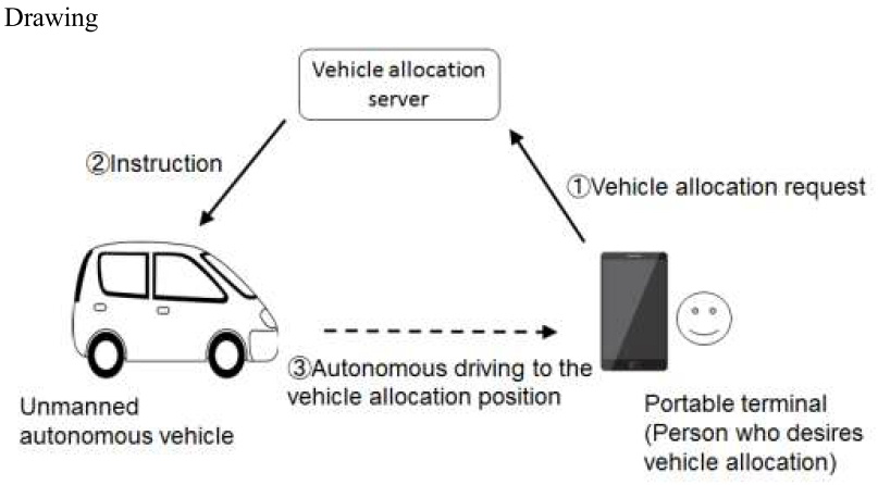
[Description of the embodiments] A plurality of unmanned autonomous vehicles are disposed in a state in which the unmanned autonomous vehicles can freely travel within a predetermined site. A plurality of unmanned autonomous vehicles, a vehicle allocation server, and a portable terminal can communicate with each other through the network. A user accesses the vehicle allocation server from his/her portable terminal in the site, thereby enabling an unmanned autonomous vehicle to move to the desired vehicle allocation position. The vehicle allocation server which has received the vehicle allocation request issues an instruction to the specific unmanned autonomous vehicle to travel toward the vehicle allocation position through the network. After arriving at the vehicle allocation position through the autonomous driving, the unmanned autonomous vehicle urges the user to get on the unmanned autonomous vehicle. Accordingly, the user can move to the destination within the site in a sense of using a taxi.
[Conclusion] The invention of Claim 1 does not fall under "invention."
The invention of Claim 2 does not fall under "invention."
[Explanation] The invention of Claim 1 and 2 recites "unmanned autonomous vehicles." However, the invention of Claim 1 and 2 does not recite neither the control of the unmanned autonomous vehicles or the information processing performed by the unmanned autonomous vehicles at all.
Therefore, the invention of Claim 1 and 2 does not fall under neither of (a) those concretely performing control of an apparatus or processing with respect to the control or (b) those concretely performing information processing based on the technical properties such as physical, chemical, biological or electric properties of an object described in "Examination Guidelines Part III, Chapter 1: Eligibility for Patent and Industrial Applicability 2.2 (2)".
Then, it is determined “whether or not information processing by software is concretely realized by using hardware resources”. Claim 1 and 2 specifies that a system comprising a vehicle allocation server, a portable terminal, and an unmanned autonomous vehicle is used. However, it is specified merely “when the vehicle allocation server receives a vehicle allocation request for the unmanned autonomous vehicle for which a vehicle allocation position is specified from the person who desires the vehicle allocation, the vehicle allocation server allocates unmanned autonomous vehicle to the person who desires the vehicle allocation” and no information processing is specified. Therefore, it is not possible to determine that concrete means or procedures for specific calculation or processing of information depending on the intended use which is an allocation of unmanned autonomous vehicles, is specified. For this reason, in the invention of Claim 1 and 2, a specific information processing system or an operation method thereof depending on intended use is not constructed through cooperation of software and hardware resources.
Therefore, since the information processing by software is not concretely realized by using hardware resources, the invention of Claim 1 and 2 is not a creation of the technical idea utilizing a law of nature, and thus does not fall under “invention”.
[Measures of the applicant] It is not possible to resolve the reason of refusal.
(Supplementary explanation)
In the detailed description of the invention, it is described merely “A plurality of unmanned autonomous vehicles, a vehicle allocation server, and a portable terminal can communicate with each other through the network” or “A user accesses the vehicle allocation server from his/her portable terminal in the site, thereby enabling an unmanned autonomous vehicle to move to the desired vehicle allocation position”, etc. Furthermore, it is not described specific calculation or processing of information depending on the intended use which is an allocation of unmanned autonomous vehicles. Therefore, it is not possible to amend the Claim 1 and 2 to be “the information processing by software is not concretely realized by using hardware resources”.
[Case 2-11] Tree-Structured Area Management Data
Title of Invention
Tree-Structured Area Management Data, Contents Data Distribution Method and Contents Data
What is claimed is:
[Claim 1] Tree-structured area management data comprising in the order of single-layer root node, multi-layer intermediate nodes and single-layer leaf nodes from the top, wherein;
the said leaf nodes have location information on distribution areas and contents data;
among the said intermediate nodes, those equipped with the said plurality of leaf nodes underneath have pointers to the said plurality of leaf nodes underneath and location information having a minimum bounding rectangle that bounds the said plurality of distribution areas corresponding to the plurality of leaf nodes underneath with the minimum area;
among the said intermediate nodes, those equipped with a plurality of intermediate nodes underneath have pointers to the said plurality of intermediate nodes underneath and location information of the minimum bounding rectangle that bounds the said minimum bounding rectangles owned by the plurality of intermediate nodes underneath with the minimum area;
the said root node has pointers to the said plurality of intermediate nodes underneath;
wherein the tree-structured area management data is stored in a contents distribution server; and
it is used by the said contents distribution server to perform processing to identify leaf nodes corresponding to distribution areas that geographically bound current location information input as a search key in accordance with the pointers owned by root node or intermediate nodes.
(Claim 1: Falls under "invention.")
[Claim 2] A contents data distribution method wherein; a contents distribution server that stored the tree-structured area management data described in Claim 1
acquires current location information as a search key;
identifies intermediate nodes corresponding to the minimum bounding rectangle that geographically contain the said current location information by comparing location information of the minimum bounding rectangle owned by the said plurality of intermediate nodes underneath the said root nodes with the said current location information;
repeats a comparison of location information of the minimum bounding rectangle owned by the said plurality of subordinate intermediate nodes of the said identified intermediate nodes or location information of the said distribution areas owned by the said plurality of leaf nodes with the said current location information until leaf nodes corresponding to distribution areas that geographically contain the said current location information are identified; and
distributes contents data owned by the said identified leaf nodes to users.
(Claim 2: Falls under "invention.")
[Claim 3] The contents data distribution method described in Claim 2 wherein the said contents data relates to data on items or characters used on gaming applications that run on gaming machines of users.
(Claim 3: Falls under "invention.")
[Claim 4] The contents data distributed to users by means of the method described in Claim 3.
(Claim 4: Does not fall under "invention.")
Overview of the description
[Technical Field] The present invention relates to a data structure for a technology to distribute contents data to users.
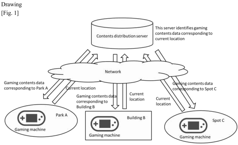
[Background Art] As described in Fig.1, there is a service for users who own gaming machines that run on specific gaming applications within specific distribution areas on a map to distribute contents data on gaming related to the distribution areas to their gaming machines. In this service, if a user is found to be in a specific distribution area while he/she is in transit, contents data related to the distribution area is automatically distributed to his/her gaming machine. Moreover, it is envisaged that the user physically moves to a specific distribution area where he/she may receive desired contents data in order to acquire it.
[Problems to be solved by the invention] However, in order to increase a game element of those applications, it is necessary to set an enormous number of distribution areas. In the conventional techniques, it was required to compare location information on all distribution areas and current location of users so as to identify distribution areas that geographically contain current location of users. This required large computing burden.
[Solution for the Problem to be solved] (Omitted)
[Description of the embodiments] The contents distribution server acquires current location information of users from their gaming machines as a search key, identifies distribution areas that geographically contain the current location information, and distributes contents data corresponding to the identified distribution areas to users. The gaming machines are equipped with the communication function and current location acquisition function. Contents data includes those related to items and characters used on gaming applications that run on those gaming machines. The contents distribution server manages distribution areas and contents data in a way that they are included in tree-structured area management data as described below and stored in a memory part thereof.
(Data Structure of Area Management Data)
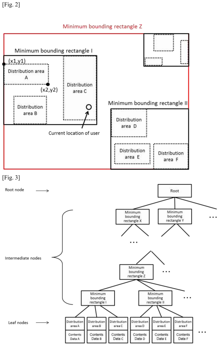
Each distribution area defines location information based on information on latitude and longitude (x1, y1) (x2, y2) in the rectangular diagonal position. A distribution area is bounded by one minimum bounding rectangle together with one or more distribution areas nearby. The minimum bounding rectangle refers to a rectangle that bounds a plurality of distribution areas with the minimum area and defines location information based on information on latitude and longitude in the rectangular diagonal position in the same manner as distribution areas. A minimum bounding rectangle is bounded by a superordinate minimum bounding rectangle together with one or more minimum bounding rectangles nearby. In this way, a tree-structure composed of a plurality of distribution areas and minimum bounding rectangles is formed.
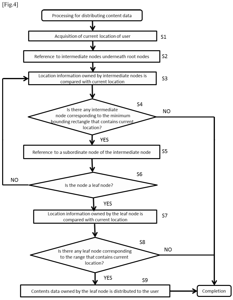
A root node is in the uppermost position of data structure. Nodes corresponding to minimum bounding rectangles are called intermediate nodes, while those corresponding to distribution areas are called leaf nodes. A root node has pointers to a plurality of intermediate nodes underneath. Each intermediate node has location information on a corresponding minimum bounding rectangle and a pointer to a plurality of subordinate intermediate nodes or leaf nodes. Each leaf node has location information on corresponding distribution areas and contents data.
Fig.2 is an illustrative example of distribution areas and minimum bounding rectangles. The distribution areas A - C are bounded by the minimum bounding rectangle I and the distributions areas D - F by the minimum bounding rectangle II.
Fig.3 represents a structure of area management data formed in the case of Fig.2. The intermediate node corresponding to the minimum bounding rectangle I has pointers to the leaf nodes corresponding to the distribution areas A - C, while that corresponding to the minimum bounding rectangle II has the leaf nodes corresponding to the distribution areas D - F. The uppermost root node has pointers to each of the intermediate nodes. Contents data is associated with each of the leaf nodes.
(Processing for Contents Data Distribution)
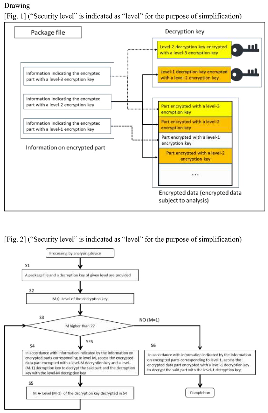
Fig.4 is used to explain processing for distributing contents data performed by the contents distribution server. Once the server acquires current location information of a user from his/her gaming machine as a search key (S1), it refers to the intermediate nodes underneath the root node (S2) and compares location information owned by the intermediate nodes with current location information (S3). Based on this comparison, it is determined whether or not there is any node corresponding to the minimum bounding rectangle that geographically contains current location information (S4), and if that is the case, subordinate nodes of the intermediate nodes are referred to (S5). If there is no such node, it is determined that there are no users in any of the distribution areas, and the processing completes and processing for distributing contents data is not performed. Then, whether or not the subordinate nodes of the intermediate nodes are leaf nodes is determined (S6). If they are not leaf nodes, that is, if they are intermediate nodes, the process returns to S3 and the procedures of S3 - S5 are repeated until those nodes reach a leaf node. If they are found to be leaf nodes, location information on distribution areas owned by the leaf nodes and current location information are compared (S7) to determine whether or not there is any leaf node corresponding to distribution areas that geographically contain current location information (S8). If there is such a leaf node, contents data owned thereby is distributed to users (S9). On the other hand, if there is no such leaf node, it is determined that there are no users in any of the distribution areas, and the processing completes and processing for distributing contents data is not performed.
Specific processing for distributing contents data is shown using the examples in Figs. 2 and 3. In these examples, a user exists in the distribution area C. By repeating process of comparing location information on distribution areas owned by the root node and intermediate nodes with current location information, it is determined that current location information is contained geographically in the minimum bounding rectangle I. Then, location information on the distribution areas A - C owned by a subordinate leaf node of the intermediate node corresponding to the minimum bounding rectangle I is compared with current location information to determine whether or not it is contained geographically in the distribution area C. Therefore, contents data owned by the leaf node corresponding to the distribution area C is distributed to users.
As discussed here, the management of distribution areas with tree-structure only requires the processing of comparison for the number of stages of the tree-structure in order to identify distribution areas that geographically contain current location information of users that was input as search keys. As a result, this method may identify distribution areas at higher speed compared to the conventional technique of comparing location information on all distribution areas with current location of users.
[Conclusion] The inventions of Claim 1-3 fall under "invention."
The invention of Claim 4 does not fall under "invention."
[Explanation]
- Claim 1
The area management data of Claim 1 is data having a structure capable of identifying distribution areas that geographically contain current location information input as a search key by means of information processing in accordance with pointers owned by root nodes and intermediate nodes. Thus, the “structured data” has similar properties to the computer program in that a structure of the data prescribes information processing by computer so that this structured data is determined to be equivalent to the computer program.
Moreover, it is determined, from the statement of Claim 1, that computing or processing of specific information in accordance with its purpose of use, that is, the identification of distribution areas including current location input as a search key, is realized by concrete means or procedures, that is, a series of information processing by the contents distribution server that stores area management data by means of the collaboration between the software (“structured data” equivalent to the computer program) and hardware resources. The “structured data” is thus determined to establish an operating method of a specific information processing device in accordance with the purpose of use by means of the collaboration between the software and hardware resources.
Therefore, as information processing prescribed by the “structured data” equivalent to the computer program is concretely realized using hardware resources, the area management data of Claim 1 is a creation of the technical idea utilizing a law of nature and thus falls under “invention”.
- Claim 2
It is determined, from the description of Claim 2, that computing or processing of specific information in accordance with its purpose of use, that is, the distribution of contents data in accordance with current location input as a search key, is realized by concrete procedures, that is, a series of information processing by the contents distribution server that stores area management data, by means of the collaboration between the software and hardware resources. The method of Claim 2 is thus determined to establish an operating method of a specific information processing device in accordance with the purpose of use by means of the collaboration between the software and hardware resources.
Therefore, as information processing by the computer program is concretely realized using hardware resources, the method of Claim 2 is a creation of the technical idea utilizing a law of nature and thus falls under “invention”.
- Claim 3
Since Claim 3 cites Claim 2, it is determined, from the description of Claim 3, that computing or processing of specific information in accordance with its purpose of use, that is, the distribution of contents data in accordance with current location input as a search key, is realized by concrete procedures, that is, a series of information processing by the contents distribution server that stores area management data by means of the collaboration between the software and hardware resources in the same manner as the determination made in Claim 2. The method of Claim 3 is thus determined to establish an operating method of a specific information processing device in accordance with the purpose of use by means of the collaboration between the software and hardware resources.
Therefore, as information processing by the computer program is concretely realized using hardware resources, the method of Claim 3 is a creation of the technical idea utilizing a law of nature and thus falls under “invention”.
- Claim 4
Mere presentation of information (where the feature resides solely in the content of the information, and the main object is to present information), such as presentation of information (presentation per se, means for presentation or method of presentation) in which a technical feature does not reside, does not fall under "invention" ("creation of the technical idea utilizing a law of nature") mentioned in the main paragraph of Article 29(1).
The contents data of Claim 4 relates to data on items or characters used on gaming applications that run on gaming machines of users. The only thing identified is that such data is distributed from the contents distribution server to users. The distribution processing and the distribution method do not have any technical features. Therefore, the contents data of Claim 4 does not have technical features in the presentation of information (presentation per se, means for presentation or method of presentation), its feature resides solely in the content of the information that “it is data on items or characters used on gaming applications that run on gaming machines of users”, and its main object is to present information. Moreover, since the contents data is owned only by the leaf nodes of area management data and its structure does not prescribe any information processing by computers, it does not fall under “structured data” equivalent to the computer program either.
Therefore, since the contents data of Claim 4 is mere presentation of information, it is not a creation of the technical idea utilizing a law of nature as a whole and thus does not fall under “invention”.
[Measures of the applicant] It is understood that regarding the contents data its feature resides solely in the content of information and that it is not equivalent to the computer program as far as the description etc. are referred to. Therefore, the contents data of Claim 4 cannot overcome the reason for refusal.
[Case 2-12] Data Structure of Encrypted Package File
Title of Invention
Data Structure of Encrypted Package File
What is claimed is:
[Claim 1] A data structure of a package file comprising; encrypted data in which each part of data subject to analysis is encrypted with an encryption key in accordance with a security level 1 - N (N refers to an integer higher than 2) of the part;
a plurality of encrypted decryption keys whose security level is 1 - (N-1) encrypted with encryption keys whose security level is one level higher than them; and
information on the said encrypted data part encrypted with the said encryption keys and on encrypted parts indicating the said encrypted decryption keys, wherein;
an analyzing device equipped with a memory part that stores the said package file and decryption keys whose security level is any of 1 - N and a decryption unit that decrypts data with the said decryption keys; and
it is used to repeat a process in which the analyzing device, in accordance with information indicated by the said information on encrypted parts, decrypts and acquires parts that can be decrypted with the said decryption keys and encrypted decryption keys whose security level is one level lower among the said encrypted data until the device decrypts and acquires encrypted decryption keys of security level 1.
(Claim 1: Falls under "invention.")
Overview of the description
[Technical Field] The present invention relates to a data structure that encrypts data subject to analysis including parts of different security levels.
[Background Art] In response to the progress of IoT technology in recent years, it has become possible to collect bulk data (so called big data) on the status of operation of devices and behaviors of individuals (histories of movement, purchase, etc.) acquired from various sensors. The study on analytical techniques has become popular to analyze such big data and obtain useful knowledge. On the other hand, since such data includes a great deal of confidential information of enterprises and personal information of individuals, sufficient care should be taken to protect security when data subject analysis is provided to data analysts.
As one of security measures, there is a system that allows data provider to set a plurality of security levels for each part of data subject to analysis and for data analysts to whom data is provided. In this case, each part of data subject to analysis is encrypted with an encryption key in accordance with its security level, while a plurality of decryption keys whose security levels are lower than those set for analysts are provided thereto. Data analysts decrypt parts for which security levels lower than those set therefor in the data subject to analysis using the decryption keys provided. For example, we suppose a case where security level 3 is set for information on “addresses”, security level 2 for information on “names”, and security level 1 for other parts in the data subject to analysis, and data is encrypted with encryption keys in accordance with their security level and then provided to data analysts. In this case, decryption keys of levels 1 - 3 are provided to data analysts of security level 3 so that they may decrypt the whole data subject to analysis for their analysis. Decryption keys of levels 1 and 2 are provided to data analysts of security level 2 so that they may decrypt parts other than information on “addresses” for their analysis.
[Problems to be solved by the invention] In the conventional encryption system mentioned above, data analysts had to own a plurality of decryption keys in accordance with the number of several security levels. This caused burden for data analysts and the management of decryption keys was complicated.
[Solution for the Problem to be solved] In the present invention, only one decryption key is provided originally to data analysts regardless of their security level by providing data analysts with package files that add a plurality of encrypted decryption keys and information on encrypted parts to data subject to analysis encrypted in accordance with security levels. That is, although data analysts originally have only one decryption key, they may decrypt data parts within the range in accordance with their security level with respect to encrypted data encrypted with a plurality of encryption keys of different security levels.
The specific embodiment is explained below. It is supposed that there are three security levels (1 - 3).
(Data Structure of Package File)
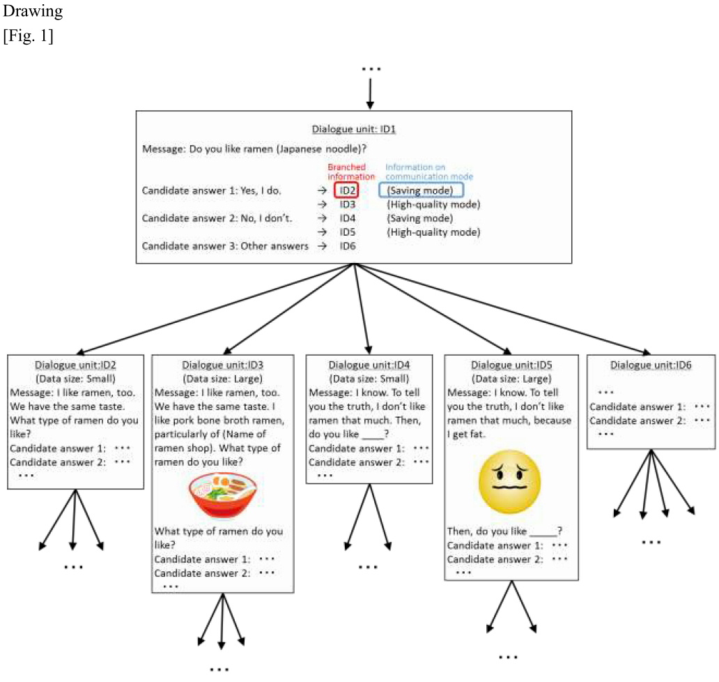
Fig. 1 shows one example of data structure of package files. A data administrator creates a package file under the following procedures based on data subject to analysis he/she has in order to provide an analyst therewith. As a simple example of data subject to analysis, there is a document file in which security levels are set for each paragraph considering the paragraphs as “parts”, but not limited thereto. For example, if data subject to analysis is a structured document, a system to set security levels for each part defined by a specific tag (“address” tag, etc.) is conceivable. Data subject to analysis may be images or music data.
Firstly, the respective parts of data subject to analysis are encrypted with separate encryption keys in accordance with their security levels (1 - 3) and included in the package file as encrypted data.
Then, decryption keys corresponding to the plurality of encryption keys used for the said encryption are encrypted with encryption keys whose security levels are one level higher than them. However, decryption keys of the highest security level are not encrypted. In this embodiment, decryption keys of security levels 1 and 2 are encrypted with encryption keys of security levels 2 and 3, respectively. The plurality of encrypted decryption keys is included in the package file as encrypted decryption keys.
Lastly, information on encrypted parts indicating parts of the said encrypted data encrypted with encryption keys of those security levels and the said encrypted decryption keys is created for each security level, and included in the package file. Specifically, “information indicating parts encrypted with encryption keys of security level 3” includes address of data subject to analysis encrypted with encryption keys of security level 3 and decryption keys of security level 2 encrypted with encryption keys of security level 3 in the package file.
(Information Processing by Analyzing Device)
A data administrator provides a data analyst with the said package file created and one decryption key of a security level set therefor.
An analyzing device owned by the data analyst is equipped with a memory part to store the package file and the decryption key of any of the security levels (1 - N) and a decryption part to decrypt data using decryption keys. By decrypting the said package file using the said decryption key of any of the security levels acquired, the data analyst obtains data subject to analysis in accordance with his/her security level. Specific information processing performed by the analyzing device is explained as follows (Fig. 2).
S1: The analyzing device acquires the said package file and given decryption key of any of the security levels and stores it in the memory part.
S2: A security level of the said one decryption key acquired is set to be M.
S3: If M is 2 or higher, the processing described in S4 is performed. If M is 1, the processing described in S6 is performed.
S4: In accordance with information indicated by the said information on encrypted parts corresponding to security level M, access an encrypted data part encrypted with an encryption key of security level M and an encrypted decryption key of security level (M-1) to decrypt the said part and the encrypted decryption key with a decryption key of security level M.
S5: A security level (M-1) of the decryption key decrypted in S4 is newly set as M and the process returns to S3.
S6: In accordance with information indicated by the said information on encrypted parts corresponding to security level 1, access the encrypted data part encrypted with an encryption key of security level 1 to decrypt the said part with a decryption key of security level 1.
[Effect of Invention] The present invention can simplify the management of decryption keys, because an analyzing device sequentially decrypts encrypted parts and decryption keys of subordinate security levels so that it is possible to decrypt parts of data in accordance with security levels of the device, although only one decryption key regardless of the security level is provided to data analysts.
[Conclusion] The inventions of Claim 1 falls under "invention."
[Explanation]
- Claim 1
The data structure of package file of Claim 1 can be said to be a data structure which enables the processing of decrypting encrypted parts and decryption keys of subordinate security levels sequentially, from its statement that “an analyzing device equipped with a memory part that stores the said package file and decryption keys whose security level is any of 1 - N and a decryption unit that decrypts data with the said decryption keys; and it is used to repeat a process in which the analyzing device, in accordance with information indicated by the said information on encrypted parts, decrypts and acquires parts that can be decrypted with the said decryption keys and encrypted decryption keys whose security level is one level lower among the said encrypted data until the device decrypts and acquires encrypted decryption keys of security level 1.” Since the data structure has similar properties to the computer program in that it prescribes information processing performed by an analyzing device, it is equivalent to the computer program (computer software).
Moreover, we may determine, from the statement of Claim 1, that computing or processing of specific information in accordance with its purpose of use, that is, an analyzing device having one decryption key sequentially decrypts encrypted parts and decryption keys of subordinate security levels and thereby decrypting the decryption of data parts in accordance with security levels of the analyzing device, is realized by concrete means or specific procedures, that is, a series of information processing by the analyzing device by means of the collaboration between the software (data structure equivalent to the computer program) and hardware resources. The data structure is thus determined to establish an operating method of the specific information processing device in accordance with the purpose of use by means of the collaboration between the software and hardware resources.
Therefore, as information processing prescribed by the data structure equivalent to the computer program is concretely realized using hardware resources, the data structure of Claim 1 is a creation of the technical idea utilizing a law of nature and thus falls under “invention.”
[Case 2-13] Data Structure of Dialogue Scenarios in Voice Interactive System
Title of Invention
Data Structure of Dialogue Scenarios in Voice Interactive System
What is claimed is:
[Claim 1] A data structure of dialogue scenarios utilized in a voice interactive system composed of a client’s device and a server, comprising:
unit IDs that identify dialogue units constituting dialogue scenarios;
messages including contents of utterances and information presented to users;
a plurality of candidate answers in response to answers from users;
information on communication mode; and
a plurality of branch information mapped to each of the candidate answers and information on communication mode, wherein the branch information indicates the following dialogue unit which contains messages corresponding to the said candidate answers and whose data size is corresponding to the said information on communication mode;
wherein, the said data structure of dialogue scenarios is utilized for the following processing performed by the said client’s device:
(1) Outputting a message included in the current dialogue unit;
(2) acquiring an answer from the user in response to the said message;
(3) specifying the said candidate answer based on the answer from the said user;
(4) selecting one branch information based on the said candidate answer and information on communication mode; and
(5) receiving from the server a following dialogue unit indicated by the selected branch information.
(Claim 1: Falls under "invention.")
Overview of the description
[Background Art] In recent years, research and development have progressed aiming at realization of interactive artificial intelligence (AI) that gives users a feeling of actual conversations or communications. The present invention relates to a data structure of dialogue scenarios utilized in voice interactive systems to realize such interactive AI.
As one technique of voice interactive systems, we have a technique of managing contents of dialogues based on dialogue scenarios. A dialogue scenario maps the subsequent scenario to each of candidate answers from a user, and a dialogue is forwarded by selecting one of the scenarios in response to an answer from the user. For example of dialogue scenarios, in the case where a user is asked, “do you like ramen?”, a voice dialogue is performed by selecting different scenarios according to positive answers (the user likes ramen) or negative answers (the user does not like ramen) from the user. When a dialogue scenario is created, it is possible to utilize a collection of natural and human dialogue patterns generated by collecting corpus data on actual dialogues from comments posted on websites or social networking services and by analyzing and learning such data with the use of natural language processing technologies such as morphological analysis and syntax analysis.
Voice interactive systems are widely utilized in smartphones, etc. In this case, dialogue scenarios are usually managed by voice dialogue servers.
[Problems to be solved by the invention] However, conventional voice interactive systems do not give any consideration to the capacity of communications with servers. The monthly capacity of communications is often restricted in the case of communication systems including smartphones. The capacity of communications differs from one price plan to another selected by users. While some users whose monthly capacity of communication is small want to enjoy voice dialogues consuming a small capacity of communications, other users whose monthly capacity of communications is large expect to enjoy high-quality voice dialogues.
The present invention aims to provide a data structure that allows users to select dialogue scenarios adapted to communication capacities they look for.
[Description of the embodiments]
(Overall Structure)
A dialogue scenario describes how a dialogue continues in the tree shape and one unit of dialogue is herein called “dialogue unit”. The overall dialogue scenario is stored in a memory part of a server and sent to a client’s terminal by dialogue unit. The client’s terminal is equipped with a well-known composition such as CPU, memory, touch screen, microphone and speaker. The well-known composition realizes various functions including the function to communicate with the server, the function to store dialogue units received from the server, the function of playing messages included in dialogue units in the form of audio output and image display, and the function of receiving answers from users to messages in the form of voice, character entry, etc.
(Data Structure)
Fig. 1 illustrates one example of data structure of a dialogue scenario. Each of the dialogue units that constitutes the dialogue scenario contains data including, unit IDs, messages indicating contents of utterances to users and information presented, a plurality of candidate answers in response to answers from users, information on communication mode (“saving mode” or “high-quality mode”) and a plurality of branch information mapped to each of the candidate answers and information on communication mode, wherein the branch information indicates the following dialogue unit which contains messages corresponding to the said candidate answers and whose data size is corresponding to the said information on communication mode. The said messages may be mere contents of utterances to be played in audio (Dialogue ID2 or ID4 in Fig. 1) or presented information such as images to be displayed together with audio output reproduction (Dialogue ID3 or ID5 in Fig. 1). Thus, the data size of dialogue units differs greatly depending on contents of messages included in dialogue units. In cases where the data size of following dialogue units indicated by the branch information is small, “saving mode” is mapped to the branch information. In cases where the data size of dialogue units indicated by the branch information is large, “high-quality mode” is mapped to the branch information for management. By this way, a plurality of options can be offered as candidates of following dialogue units in response to one candidate answer, in accordance with the capacity of communications.
(Information Processing in Voice Interactive System)
Firstly, after one dialogue unit is distributed to a client’s terminal, a message in the dialogue unit is played with the client’s terminal. When the client’s terminal acquires an answer from the user to the message, the candidate answer is specified based on the answer. The specification is executed, for example, by specifying the most similar candidate answer to the answer from the user through a matching of strings relating to the answer from the user with strings relating to candidate answers. Then, one branch information is selected from a plurality of branch information corresponding to the specified candidate answer. The details of how to select branch information will be described below. When the selected branch information is sent to the server, a following dialogue unit indicated by the branch information is sent to the client’s device from the server. A voice interactive system is realized by repeating this processing.
(Selection of Branch Information)
In the present voice interactive system, the communication mode of clients’ terminals is set as “saving mode” or “high-quality mode”. A communication mode may be set automatically in accordance with price plans of clients’ terminals or the status of communications, or manually by users. It is also possible to switch a mode where necessary during voice dialogues. In cases where “saving mode” is set for clients’ terminals, branch information mapped to “saving mode” is selected, while in cases where “high-quality mode” is set, branch information mapped to “high-quality mode” is selected. By this way, in cases where “saving mode” is set, voice dialogues may be realized in a small communication capacity, since dialogue units whose data size is small are sent sequentially to the clients’ devices. On the other hand, in cases where “high-quality mode” is set, the user may enjoy high-quality voice dialogues, since dialogue units whose data size is large are sent sequentially to the clients’ devices.
(Other Embodiments)
In the above embodiment, the case where there are only two communication modes, “saving mode” and “high-quality mode” is explained, but not limited thereto. More detailed setting of communication capacity may be allowed by offering three or more communication modes.
[Conclusion] The inventions of Claim 1 falls under "invention."
[Explanation]
- Claim 1
It can be said that the data structure of Claim 1 enables information processing, that is for voice dialogues based on branch information included in dialogue units, from the statement of Claim 1 that “the said data structure of dialogue scenarios is utilized for the following processing performed by the said client’s device:
(1) Outputting a message included in the current dialogue unit;
(2) acquiring an answer from the user in response to the said message;
(3) specifying the said candidate answer based on the answer from the said user;
(4) selecting one branch information based on the said candidate answer and information on communication mode; and
(5) receiving from the server a following dialogue unit indicated by the selected branch information”. Since the data structure has similar properties to the computer program in that it defines information processing performed in voice interactive systems, it is equivalent to the computer program (computer software).
Moreover, it can be determined, from the statement of Claim 1, that computing or processing of specific information in accordance with its purpose of use, that is, voice dialogues in accordance with branch information included in dialogue units, is realized by concrete means or procedures, that is, a series of information processing by a voice interactive system composed of the server and clients’ devices by means of the collaboration between the computer software (data structure equivalent to the computer program) and hardware resources. The data structure is thus determined to establish an operating method of the specific information processing device in accordance with the purpose of use by means of the collaboration between the computer software and hardware resources.
Therefore, as information processing prescribed by the data structure equivalent to the computer program is concretely realized utilizing hardware resources, the data structure of Claim 1 is a creation of the technical idea utilizing a law of nature and thus falls under “invention”.
[Case 2-14] Trained Model for Analyzing Reputations of Accommodations
Title of Invention
Trained Model for Analyzing Reputations of Accommodations
What is claimed is:
[Claim 1] A trained model for causing a computer to function to output quantified values of reputations of accommodations based on text data on reputations of accommodations, wherein;
the model is comprised of a first neural network and a second neural network connected in a way that the said second neural network receives output from the said first neural network;
the said first neural network is comprised of an input layer to intermediate layers of a feature extraction neural network in which the number of neurons of at least one intermediate layer is smaller than the number of neurons of the input layer, the number of neurons of the input layer and the number of the output layer are the same, and weights were trained in a way each value input to the input layer and each corresponding value output from output layer become equal;
weights of the said second neural network were trained without changing the weights of the said first neural network; and
the model causes the computer function to perform a calculation based on the said trained weights in the said first and second neural networks in response to appearance frequency of specific words obtained from the text data on reputations of accommodations input to the input layer of the said first neural network and to output the quantified values of reputations of accommodations from the output layer of the said second neural network.
(Claim 1: Falls under "invention." (Falls under "invention" as a "program", even though the claimed subject matter is described as a "trained model."))
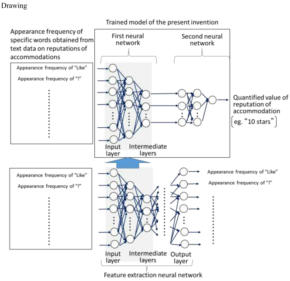
Overview of the description
[Background Art] A neural network, which has a computer function as a computing unit to calculate output in response to certain input, is capable of performing complicated information processing at high speed by being trained from a number of actual examples. Therefore, people intend to use neural networks for various purposes in such fields as image recognition, voice recognition, voice synthesis and automated translation.
Generally, in cases where neural networks are utilized in new areas, in many cases it is not clear what should be input as the input feature values, therefore, it is necessary to carefully review what should be selected as the input feature values accordingly.
In order to analyze text data on reputations of accommodations such as hotels posted on travel review sites with neural networks, it is not straightforward to select the input feature values, because the appearance frequencies of a variety of words (“Like”, “!”, etc.) included in the text data can be considered as the candidate input feature values.
[Problems to be solved by the invention] The present invention has been conceived in view of the above problems into consideration and aims to accurately analyze reputations of accommodations even if the input feature values are not properly pre-selected.
[Solution for the Problem to be solved] The trained model of the present invention aims to cause a computer to function to output quantified values of reputations of accommodations based on text data on reputations of accommodations and is comprised of a first neural network and a second neural network connected in a way that the second neural network receives output from the first neural network. The trained model is supposed to be utilized as a program module which constitutes a part of artificial intelligence software.
The trained model of the present invention is utilized in a computer equipped with a CPU and a memory. Specifically, the CPU of the computer operates, in accordance with instructions from the trained model stored in the memory, in a way that it performs a calculation based on trained weights and response functions in the first and second neural networks in response to data input to input layers of the first neural network (appearance frequency of specific words obtained from text data of reputations of accommodations, e.g. by performing morphological analyses) and outputs results from output layers of the second neural network (quantified values of reputations, e.g. “10 stars”).
The first neural network is comprised of an input layer to intermediate layers of a feature extraction neural network. This feature extraction neural network is generally called autoencoder. In this network, the number of neurons in the intermediate layers is smaller than the number of neurons in the input layer. The number of neurons in the input layer and the number of neurons in the output layers are set to be equal. Moreover, a response function of each of the neurons in the input and output layers is a linear function, and other response functions of each of the neurons are sigmoid functions (1/(1+exp(-x))).
The feature extraction neural network is trained by means of a well-known art called back propagation method and weights between neurons are updated. In the embodiment of present invention, this neural network is trained to minimize mean square errors for overall input data so that data (each appearance frequency of a plurality of words obtained from text data on reputations of accommodations by performing morphological analyses) is input in the input layers and data the same as this input data is output from the output layers. Since sigmoid functions which are non-linear functions are utilized as neuron’s response functions as explained earlier, the weights between neurons are not symmetrical across the intermediate layer. As the feature extraction neural network is trained, the intermediate layer become possible to obtain the feature values indicating characteristics of each input data. Although the feature values that appear in the intermediate layer do not necessarily have clear physical implication, those feature values are considered as what were compressed to the extent that information input to the input layer can be restored to information output from the output layer and the feature values that appear in the intermediate layer become almost similar regardless of the input feature values to the input layer. Therefore, it is not necessary to properly preselect the input feature values to the input layer any more.
In the present invention, the part from the input layer to the intermediate layers in the feature extraction neural network in which weights were trained is connected to the second neural network as the first neural network. Weights of the second neural network are trained without changing weights of the said first neural network. The training is performed by a well-known art called a back propagation method as explained earlier.
Since the trained model of the present invention is comprised of the above first and second neural networks, it can accurately analyze reputations of accommodations without presetting the feature values.
[Conclusion] The inventions of Claim 1 falls under "invention."
[Explanation]
- Claim 1
The trained model of Claim 1 is what “causes a computer to function to output quantified values of reputations of accommodations based on to text data on reputations of accommodations” as well as to what “causes the computer function to perform a calculation based on the said trained weights in the said first and second neural networks in response to appearance frequency of specific words obtained from the text data on reputations of accommodations input to the input layer of the said first neural network and to output the quantified values of reputations of accommodations from the output layer of the said second neural network.” Moreover, considering the descriptions which states that “the trained model is supposed to be utilized as a program module which constitutes a part of artificial intelligence software” and “the CPU of the computer operates, in accordance with instructions from the trained model stored in the memory, in a way that it performs a calculation based on trained weights and response functions in the first and second neural networks in response to data input to input layers of the first neural network (appearance frequency of specific words obtained from text data of reputations of accommodations, e.g. by performing morphological analyses) and outputs results from output layers of the second neural network (quantified values of reputations, e.g. “10 stars”)”, it is clear that the trained model of Claim 1 is a “program” even though the claimed subject matter of Claim 1 is described as a "model.".
Moreover, it is determined, from the statement of Claim 1, that specific calculation or processing of specific information depending on the intended use which is accurate analysis of reputations of accommodations, is implemented by concrete means or procedures on which software and hardware resources cooperate, which is for a computer to “function to perform a calculation based on the said trained weights in the said first and second neural networks in response to appearance frequency of specific words obtained from the text data on reputations of accommodations input to the input layer of the said first neural network and to output the quantified values of reputations of accommodations from the output layer of the said second neural network.” For this reason, in the trained model of Claim 1, a specific information processing system depending on intended use is constructed through cooperation of software and hardware resources.
Therefore, since the information processing by software is concretely realized by using hardware resources, the trained model of Claim 1 is a creation of the technical idea utilizing a law of nature and thus falls under “invention”.
[Case 2-15] 3D Printing Data
Title of Invention
3D Printing Data
What is claimed is:
[Claim 1] 3D printing data used in a 3D printer which laminates model materials that finally constitute a 3D-modeled object and supporting materials that support the said model materials during modeling,
wherein the 3D printing data has a structure comprising in each layer of the said 3D-modeled object:
model material data indicating the quantity and position of dispensation of the said model materials;
a model material pointer that points to data used for the following modeling of modeling based on the said model material data;
supporting material data indicating the quantity and position of dispensation of the said supporting materials; and
a supporting material pointer that points to data used for the following modeling of modeling based on the said supporting material data;
wherein (a) the model material pointer is set (a1) to point to the supporting material data of the lowermost layer that is not modeled at the time when modeling of the model material of the layer in which the modeling material pointer is included completed, in case where the model material of a next-higher layer has a protruding part in relation to the model material of the layer in which the model material pointer is included and where the supporting material of the same layer has not been modeled at the time when the modeling of the model material in which the model material pointer is included completed and, (a2) to point to the model material data of the next-higher layer, in case where the model material of the next-higher layer does not have the protruding part or where the supporting material of the same layer has been modeled at the time when the modeling completed, and
wherein (b) the supporting material pointer is set (b1) to point to the model material data of the lowermost layer that is not modeled at the time when modeling of the supporting material of the layer in which the supporting material pointer is included completed, in case where the supporting material of a next-higher layer has a protruding part in relation to the model material of the layer in which the supporting material pointer is included and where the model material of the same layer has not been modeled at the time when the modeling of the supporting material in which the supporting material pointer is included completed and, (b2) to point to the supporting material data of the next-higher layer, in case where the supporting material of the next-higher layer does not have the protruding part or where the model material of the same layer has been modeled at the time when the modeling completed; and
wherein the 3D printing data is used by a control unit of the said 3D printer for processing to acquire the model material data or the supporting material data from a memory unit of the said 3D printer in accordance with the said model material pointer or the supporting material pointer after the modeling based on the said model material data or the supporting material data.
(Claim 1: Falls under "invention.")
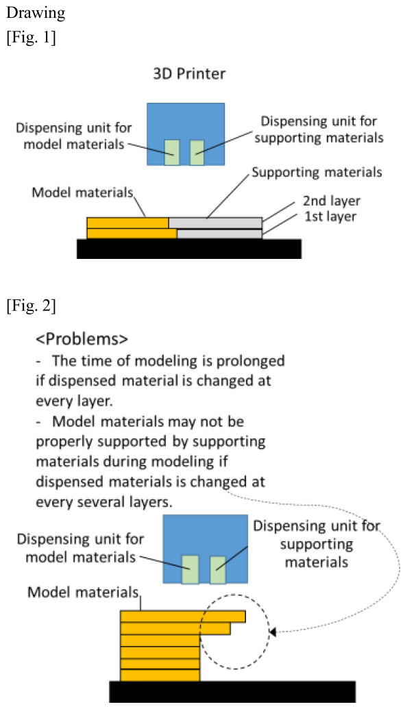
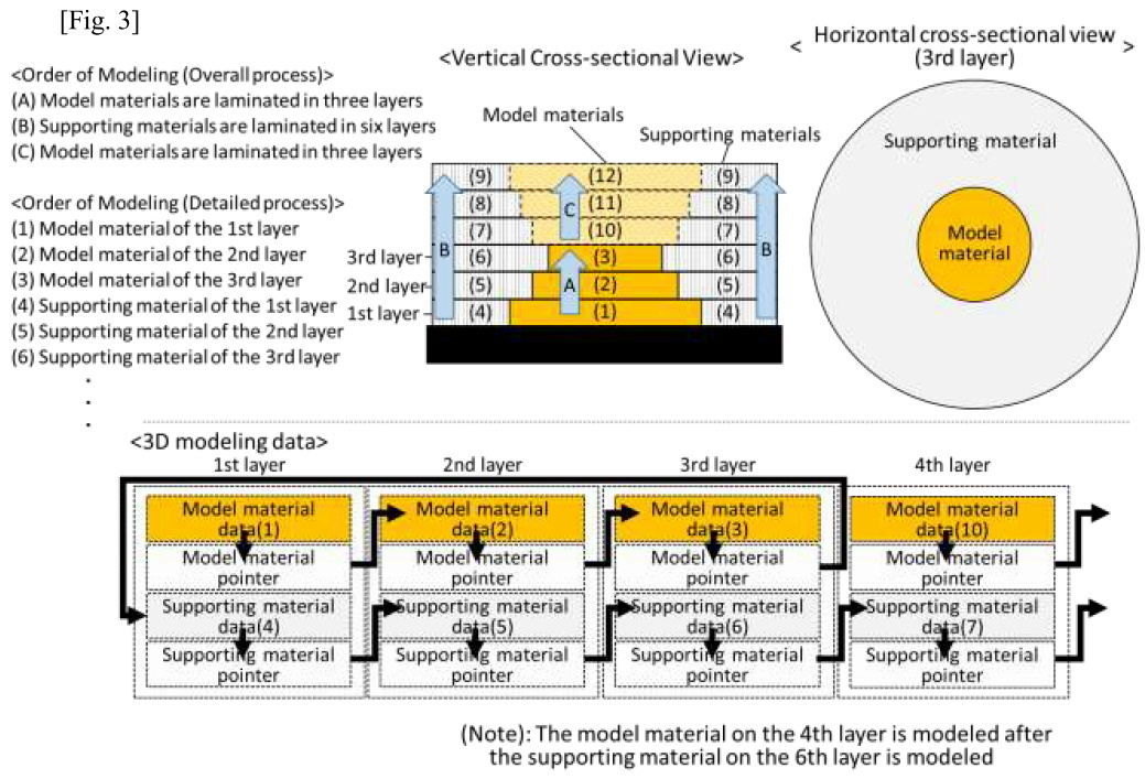
Overview of the description
[Technical Field] The present invention relates to 3D printing data.
[Background Art] A 3D printer models a 3D-modeled object by calculating data indicating a thinly-cut cross-sectional shape in the laminated direction and a position of dispensation corresponding to the cross-sectional shape based on the data on a three-dimensional shape of the 3D-modeled object, modeling each layer using model material in accordance with the data and laminating each of the layers on modeling stages.
A 3D printer (see fig. 1) is known that laminates model materials which finally constitute the 3D-modeled object and supporting materials that supports the said model materials. In case where an object to be modeled has a protruding part in relation to a lower-layer structure, the supporting materials are placed on the outer or inner circumference of the model materials to support the said protruding part of the model materials until the modeling of 3D-modeled object completes and then removed once the modeling of 3D-modeled object completes.
Such a 3D printer is comprised of a dispensing unit that dispenses model materials and a dispensing unit that dispenses supporting materials separately. After an object is modeled by dispensing model materials (or supporting materials), one layer is modeled, through changing material to be dispensed, by dispensing supporting materials (or model materials).
[Problems to be solved by the invention] In cases where dispensed material is changed at every layer as described earlier, the time of modeling is prolonged. To solve this problem, dispensed materials may be changed at every several layers.
In this case, the time of modeling is expected to be reduced due to the reduction in the number of changes, but supporting materials may not support model materials properly during modeling depending on a layout of model materials and supporting materials and the order of their modeling (see fig. 2).
The present invention has been conceived in view of those problems and aims to provide 3D printing data capable of reducing the time of modeling while appropriately laminating model material and supporting material.
[Solution for the Problem to be solved] The 3D printing data of the present invention is used, for example, in an ink-jet 3D printer that laminates model materials that finally constitute a 3D-modeled object and supporting materials that support the said model materials during modeling.
A 3D printer is equipped with a control unit that sequentially acquires model material data or supporting material data used for modeling among the 3D printing data from a memory unit in accordance with a pointer and that makes a dispensing unit to dispense materials. The 3D printer itself may be equipped with the memory unit or an external server connected to the 3D printer via a network may be equipped therewith.
The 3D printing data includes, together with model material data and supporting material data of each layer, a pointer that points to data used for a modeling following a modeling based on the model material data or the supporting material data. The model material data and the supporting material data indicate materials (model materials or supporting materials) dispensed from the dispensing unit of the 3D printer and the position and quantity of dispensation.
Now the pointer is explained. (a) The model material pointer is set (a1) to point to the supporting material data of the lowermost layer that is not modeled at the time when modeling of the model material of the layer in which the modeling material pointer is included completed, in case where the model material of a next-higher layer has a protruding part in relation to the model material of the layer in which the model material pointer is included and where the supporting material of the same layer has not been modeled at the time when the modeling of the model material in which the model material pointer is included completed and, (a2) to point to the model material data of the next-higher layer, in case where the model material of the next-higher layer does not have the protruding part or where the supporting material of the same layer has been modeled at the time when the modeling completed. (b) The supporting material pointer is set (b1) to point to the model material data of the lowermost layer that is not modeled at the time when modeling of the supporting material of the layer in which the supporting material pointer is included completed, in case where the supporting material of a next-higher layer has a protruding part in relation to the model material of the layer in which the supporting material pointer is included and where the model material of the same layer has not been modeled at the time when the modeling of the supporting material in which the supporting material pointer is included completed and, (b2) to point to the supporting material data of the next-higher layer, in case where the supporting material of the next-higher layer does not have the protruding part or where the model material of the same layer has been modeled at the time when the modeling completed. It should be noted that, when a dispensing unit comes close to the 3D-modeled object or the modeling stage to dispense materials, the dispensing unit may collide with any of modeled layers. Therefore, materials to be dispensed may be changed after the predetermined number of layers are laminated, even in cases where a model material or supporting material does not have a protruding part in relation to a lower layer, and a pointer may be set to realize such a change. Moreover, a model material pointer (or a supporting material pointer) of the uppermost layer is, in cases where the modeling of all the supporting materials (or model materials) has not yet completed, set to point to supporting material data (or model data) of the bottommost layer, and, in cases where the modeling of all the supporting layers (or model layers) have already completed, set to indicate the completion of modeling of all the layers.
The case where an hour-glass shaped 3D-modeled object having six layers shown in fig. 3 is modeled using the pointer set in the above manner is explained hereafter (It should be noted that it is rare that the lamination completes in six layers in actual 3D printing and hundreds or thousands of layers are usually laminated. The example gives an explanation supposing that the 3D-modeled object is composed of six layers in order to explain an idea of the present invention). When such a 3D-modeled object is modeled, it is required to place supporting materials on the outer circumference of model materials. However, as model materials of the fourth to the sixth layers have protruding parts from model materials of layers directly thereunder and supporting materials of the first to the third layers have protruding parts on layers directly thereunder, it is appropriate to laminate three layers of model materials, six layers of supporting materials and then the remaining three layers of model materials.
In this case, as for pointers in the 3D printing data, model material data of the second layer is pointed after the modeling based on model material data of the first layer, model material data of the third layer is pointed after the modeling based on model material data of the second layer, and supporting material data of the first layer is pointed after the modeling based on model material data of the third layer (the same process is repeated for subsequent layers). Since data to be pointed by the pointer can be changed by simple data editing, the 3D printing data having such a structure with pointers can simply set the order of modeling, that is, the order of acquiring data, after calculating data indicating a thinly-cut cross-sectional shape in a laminated direction and the quantity and position of dispensation of each material corresponding to the cross-sectional shape based on data on three-dimensional shape of the 3D-modeled object.
Since a control unit of the 3D printer sequentially acquires from the memory unit the model material data or the supporting material data used for modeling among 3D printing data, such 3D printing data having a structure with pointers is preferable in cases where the size thereof is larger than the RAM capacity of the control unit of the 3D printer or the memory unit (and a conversion unit that converts data on 3D shapes of the 3D-modeled object into 3D printing data taking into account cross-sectional shapes and stores it in the said memory unit) is accommodated in an external server connected to the 3D printer via a network.
[Effect of Invention] The present invention is capable of reducing the time required for modeling since materials to be dispensed are changed at every several layers as well as properly laminating model materials and supporting materials.
[Conclusion] The inventions of Claim 1 falls under "invention."
[Explanation]
- Claim 1
It is determined that the 3D printing data of Claim 1 is, from its statement that “comprising in each layer of the said 3D-modeled object:” “a model material pointer that points to data used for the following modeling of modeling based on the said model material data” and “a supporting material pointer that points to data used for the following modeling of modeling based on the said supporting material data”, and “the 3D printing data is used by a control unit of the said 3D printer for processing to acquire the model material data or the supporting material data from a memory unit of the said 3D printer in accordance with the said model material pointer or the supporting material pointer after the modeling based on the said model material data or the supporting material data”, data having a structure enabling the information processing by the control unit, of acquiring data used for the following modeling from the memory unit after the modeling is performed based on the model material data or the supporting material data. Thus, this 3D printing data is structured data (computer software) equivalent to the computer program, because it has similar properties to the computer program in that it prescribes information processing by the control unit based on its own structure.
The method of concretely controlling an apparatus which is a 3D printer, or performing processing along with the control is a “creation of the technical idea utilizing a law of nature”.
The invention of Claim 1, which is the computer software for causing the control unit to carry out the above method, thus falls under “invention”.
(Reference)
For 3D printing data that does not fall under “invention”, see Case 3-3 in “Annex A, 3. Eligibility of Invention and Industrial Applicability”.
2. Cases pertinent to Novelty
[Case 35] Robot Apparatus
(1) Present application
Title of Invention
Robot Apparatus
What is claimed is:
[Claim 1]
A robot apparatus which acts on an object comprising:
at least one kind of sensor for detecting the object;
a transmission section for transmitting a query to a server in order to acquire information on the object based on an output of the sensor;
a reception section for receiving response information answering the query from the server; and
a control section storing a program which controls the operation of the robot apparatus on the basis of the received response information;
wherein the response information is the information on a type of the said object specified by the said server on the basis of information received via a network from a production facility of the said object.
[Claim 2]
A robot apparatus which acts on an object comprising:
at least one kind of sensor for detecting the object;
a transmission section for transmitting a query to a server in order to acquire information on the object based on an output of the sensor;
a reception section for receiving response information answering the query from the server; and
a control section storing a program which controls the operation of the robot apparatus on the basis of the received response information;
wherein the response information contains the attribute information and the unique identification information of each of the said object specified by the said server.
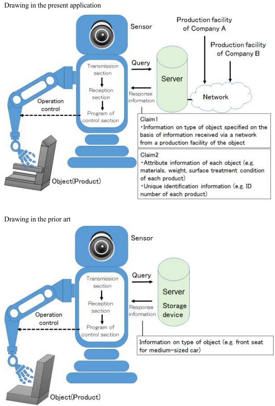
[Solution for the Problem to be Solved] The invention as claimed in Claim 1 is directed to a robot apparatus capable of accurately determining a type of a product as an object to be handled, on the basis of the latest information acquired from a production facility of the product, thereby achieving appropriate handling of the product.
The invention as claimed in Claim 2 is directed to a robot apparatus capable of achieving appropriate handling of individual products and reporting of information acquired as to the products, even when each of the products as an object to be handled has a different specification.
[Embodiment 1] In an embodiment of the invention according to Claim 1, the robot apparatus performs work such as transferring, at an assembly plant like an automobile manufacturing factory, various types of products delivered as assembly parts from a number of parts manufacturing companies. The robot apparatus has a gripping unit for grasping a product and an image sensor capable of obtaining images of the product.
In the robot apparatus, the image sensor detects, as image information, such information as the shape of a product being handled by the robot apparatus, a company name indicated on the product, a serial number assigned to each product according to a system prescribed for each type of products. The transmission section sends a query for acquiring information on a type of product to a server based on an output of the image sensor. The query contains image information.
The server is connected via a network to a computer system of a production facility of each product manufacturing company and stores the latest information on products. When the server receives the query from the robot apparatus, it analyzes the image information to specify a type of product and sends the information back to the robot apparatus as response information.
In the robot apparatus, a reception section receives the response information, and a program of a control section controls the operation of the robot apparatus on the basis of the response information.
In the present embodiment, the robot apparatus performs operation control on the basis of the information that the server received from the production facility of the product via a network. Therefore, the robot apparatus can accurately determine a type of product on the basis of the latest information. This contributes to appropriate handling of the product.
Embodiment 2
In an embodiment of the invention according to Claim 2, a robot apparatus has a gripping unit, an image sensor, and a transmission section, similar to the Embodiment 1.
In the present embodiment, the transmission section sends a server a query for identifying an individual product and acquiring relevant information based on an output of the image sensor.
The server is connected to a computer system of a production facility of each product manufacturing company via a network, and stores information on product lines in a systematically organized and continuously updated manner. When the server receives a query from the robot apparatus, it analyzes image information to identify each individual product, and sends attribute information, such as materials used, weight, and surface treatment condition of each one of the products, and unique identification information (e.g., ID number uniquely and systematically assigned to each one of all the products to be handled) to the robot apparatus as response information.
In the robot apparatus, a reception section receives the response information, and a program of a control unit controls the operation of the robot apparatus on the basis of the response information.
In this embodiment, the robot apparatus receives response information containing the attribute information, such as materials, weight, surface treatment condition, and the unique identification information of each individual product and, on the basis of the information, controls its own operation. This enables appropriate handling, etc. of each product. More specifically, this enables a control of the gripping unit in such a manner that the gripped portion of the product and the gripping force can be optimized to each individual product. Information (e.g., rigidity of the gripped portion) acquired by the control section of the robot apparatus when the gripping unit grips the product can be sent from the transmission section to the server with the unique identification information. This enables the robot apparatus to perform the feedback of such information to the server and the addition and updating of the attribute information of the product. Thus, the added or updated attribute information may be used for the next gripping of the same product, or shared with the other robot apparatus connected to the server. For the sake of the subsequent handling of the product in the assembly factory, the robot apparatus can affix to the product a seal showing a printed identification symbol or number, or attach an ID tag to the product, on the basis of the unique identification information. Furthermore, in a case where the robot apparatus detects abnormality such as damage of the product, the robot apparatus can also report it to the server with the unique identification information.
(2) Prior art
Title of Invention
Robot Apparatus
[Claim 1] A robot apparatus which acts on an object comprising:
at least one kind of sensor for detecting the object;
a transmission section for transmitting a query to a server in order to acquire information on the object based on an output of the sensor;
a reception section for receiving response information answering the query from the server; and
a control section storing a program which controls the operation of the robot apparatus on the basis of the received response information;
wherein the response information is the information on a type of the said object specified by the said server.
Overview of the description
… In the robot apparatus, an image sensor detects, as image information, such information as the shape of a product being handled by the robot apparatus, a company name indicated on the product, a serial number assigned to each product according to a system prescribed for each type of products. A transmission section sends a query for acquiring information on a type of product to a server based on an output of the image sensor. The query contains image information.
When the server receives the query from the robot apparatus, it compares the image information of the query with information stored in a storage device of the server to determine a type of object. Then, the server sends the information on the type of object, e.g., a front seat for a medium-sized car, to the robot apparatus as a response. The robot apparatus controls the operation of a gripping unit, etc. on the basis of the response information.
(3) Conclusion
The invention of Claim 1 lacks novelty.
The invention of Claim 2 has novelty.
[Explanation]
- Claim 1
The robot apparatus is a subcombination, which is a part of a combination of the robot apparatus and the server.
Claim 1 on the robot apparatus recites a feature related to the server (the other subcombination), namely, “the response information is the information on a type of the said object specified by the said server on the basis of information received via a network from a production facility of the said object”. The portion of “on the basis of information received via a network from a production facility of the said object” only describes the source from which the server, separate from the robot apparatus, obtains information for specifying response information. This does not make any difference in the program itself of the robot apparatus, and does not serve to specify a structure, a function, etc. of the robot apparatus.
Consequently, there is no difference between the invention according to Claim 1 and the invention disclosed in the cited document. As a result, the invention according to Claim 1 lacks novelty.
- Claim 2
Similarly, Claim 2 on a robot apparatus recites a feature related to the server (the other subcombination), namely, “the response information contains the attribute information and the unique identification information of each of the said object specified by the said server”. With respect to the response information, Claim 2 also specifies that the robot apparatus has “a control section storing a program which controls the operation of the robot apparatus on the basis of the received response information”. Therefore, the robot apparatus according to Claim 2 has a control section storing a program which controls the operation of the robot apparatus on the basis of the attribute information and the unique identification information of each of the object, and performs the operation, through the control section, in response to the attribute information and the unique identification information of each of the object.
In contrast, according to disclosure in the cited document, “the response information is the information on a type of the said object specified by the said server.” Therefore, the robot apparatus only has a control section with a program which controls the operation of the robot apparatus on the basis of the information on a type of the said object, vis-à-vis the response information, and does not perform operation in response to the attribute information and the unique identification information of each of the object.
Accordingly, there is a difference between the invention according to Claim 2 and the invention disclosed in the cited document. As a result, the invention according to Claim 2 has novelty.
[Case 36] Water Treatment Apparatus
(1) Present application
Title of Invention
Water Treatment Apparatus
What is claimed is:
[Claim 1] Water treatment apparatus for producing treated water by removing polluted matters contained in raw water, the apparatus comprising:
means for executing reverse cleaning process at a cycle of the variable number of days;
a concentration detector for detecting concentration of polluted matters of raw water to be introduced into the water treatment apparatus; and
means for sending the detected concentration of polluted matters to a remote control server that is communicatively connected;
wherein the remote control server calculates a new cycle of the number of days for updating on the basis of a plurality of concentrations of polluted matters received from a plurality of water treatment apparatuses on the same raw water line, and sends a result thereof to the water treatment apparatus.
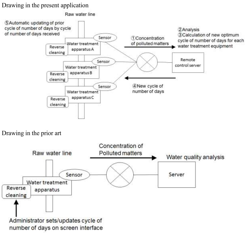
Overview of the description
The water treatment apparatus catches polluted matters contained in raw water such as ground water by a filtering bed to produce treated water. In the water treatment apparatus, as treated water is produced, ability of the filtering bed for catching polluted matters degrades. Therefore, it is necessary to execute reverse cleaning process at particular timing. It is desirable that the cycle of the number of days for executing the reverse cleaning process can be updated when water quality of raw water changes.
In the present invention, the water treatment apparatus executes the reverse cleaning process at a cycle of the variable number of days. The cycle of the number of days is updated in a case where a new cycle of the number of days is received from the remote control server.
The water treatment apparatus sends concentration of polluted matters of raw water obtained by the concentration detector to the remote control server. In the remote control server, concentrations of polluted matters received from a plurality of water treatment apparatuses existing on the same raw water line are collected and analyzed. When it is determined that water quality of the raw water line changes based on the analysis, a new optimum cycle of the number of days is calculated for each water treatment apparatus by means of a specific equation containing concentrations of polluted matters and specification information of each water treatment apparatus. Then, the remote control server sends thus calculated new cycle of the number of days of each water treatment apparatus to the respective water treatment apparatuses for the sake of automatic updating.
When the water treatment apparatus receives the new cycle of the number of days from the remote control server, the prior set cycle of the number of days is automatically updated to the new cycle of the number of days, and the reverse cleaning process is executed according to the updated cycle of the number of days after the update.
(2) Prior art
Title of Invention
Water Treatment Apparatus
[Claim 1] Water treatment apparatus for producing treated water by removing polluted matters contained in raw water, the apparatus comprising:
means for executing reverse cleaning process at a cycle of the variable number of days;
a concentration detector for detecting concentration of polluted matters of raw water to be introduced into the water treatment apparatus; and
means for sending the detected concentration of polluted matters to a server that is communicatively connected.
Overview of the description
The water treatment apparatus catches polluted matters contained in raw water such as ground water by a filtering bed to produce treated water.
As to the cycle of the number of days by which the water treatment apparatus executes the reverse cleaning process, an administrator of the water treatment apparatus can set/update, as required. The water treatment apparatus has a screen interface, and the administrator can set/update the cycle of the number of days on the screen interface.
Further, the water treatment apparatus can also send concentration of polluted matters of raw water obtained by the concentration detector to the server. The server analyzes the concentration of polluted matters, and causes a result thereof to be utilized for an examination of water quality.
(3) Conclusion
The invention of Claim 1 has novelty.
[Explanation] The invention of Claim 1 is directed to “water treatment apparatus”. Claim 1 also includes a description as to matters of the “remote control server” which is the other subcombination. That is, Claim 1 includes a description of “the remote control server calculates a new cycle of the number of days for updating on the basis of a plurality of concentrations of polluted matters received from a plurality of water treatment apparatus on the same raw water line, and sends a result thereof to the water treatment apparatus”.
When considering the common general technical knowledge at the time of filing the present application and a description of “When the water treatment apparatus receives the new cycle of the number of days from the remote control server, the prior set cycle of the number of days is automatically updated to the new cycle of the number of days, and the reverse cleaning process is executed according to the updated cycle of the number of days after the update” in the detailed description of the invention, the statement as to the other subcombination specifies the water treatment apparatus in the meaning that the water treatment apparatus has reception means for receiving the cycle of the number of days from the remote control server. Therefore, the invention of Claim 1 is specified as the water treatment apparatus having reception means.
Accordingly, the invention of Claim 1 differs from the invention of the water treatment apparatus of the cited document which only sends concentration of polluted matters to the server and does not have reception means. Therefore, the invention of Claim 1 has novelty.
[Case 37] Healthcare System and Terminal
(1) Present application
Title of Invention
Healthcare System and Terminal
What is claimed is:
[Claim 1] A healthcare system comprising a wearable sensor, a healthcare server, and a terminal device,
wherein the wearable sensor is a stick type sensor which is pasted on the skin of human body and comprises
means for measuring biological data containing a body temperature and heart rate of a wearer, and
means for sending the biological data to the terminal device;
wherein the terminal device comprises
means for receiving the biological data from the wearable sensor,
means for periodically summarizing the received biological data to send a result thereof to the healthcare server,
means for receiving a health index value A received from the healthcare server, and
means for displaying the health index value A on a screen; and
wherein the healthcare server comprises
means for calculating a health index value A of the wearer by analyzing the biological data received from the terminal device by means of analysis procedure X, and
means for sending the calculated health index value A to the terminal device.
[Claim 2] A terminal device to be used for the healthcare system of Claim 1. Drawing

(2) Prior art
Title of Invention
...
[Claim 1] A healthcare system comprising a wearable sensor, a healthcare server, and a terminal device,
wherein the wearable sensor is a clothing type sensor that a wearer wears and comprises
means for measuring biological data containing a body temperature and heart rate of the wearer, and
means for sending the biological data to the terminal device;
wherein the terminal device comprises
means for receiving the biological data from the wearable sensor,
means for periodically summarizing the received biological data to send a result thereof to the healthcare server,
means for receiving a health index value A received from the healthcare server, and
means for displaying the health index value A on a screen; and
wherein the healthcare server comprises
means for calculating a health index value A of the wearer by analyzing the biological data received from the terminal device by means of analysis procedure Y, and means for sending the calculated health index value A to the terminal device.
(Supplementary explanation)
There is no difference between the present invention and the invention disclosed in the Cited Document in that the communication system among a wearable sensor a terminal device and a healthcare server.
(3) Conclusion
The invention of Claim 1 has novelty.
The invention of Claim 2 lacks novelty.
[Explanation]
- Claim 1
The invention of Claim 1 differs from the invention disclosed in the cited document in a type of wearable sensor used in healthcare system and analysis procedure in the healthcare server.
That is, there is a difference between the invention of Claim 1 and the invention disclosed in the cited document. Therefore, the invention of Claim 1 has novelty.
- Claim 2
Claim 2 depends on Claim 1 and is directed to an invention of “terminal device”. Claim 1 describes matters as to a “wearable sensor” and a “healthcare server” which are the other subcombination. That is, Claim 1 recites a wearable sensor “which is a stick type sensor to be pasted on the skin of human body and comprises means for measuring biological data containing a body temperature and heart rate of the wearer and means for sending the biological data to the terminal device”, and a healthcare server “which comprises means for calculating a health index value A of the wearer by analyzing the biological data received from the terminal device by means of analysis procedure X and means for sending the calculated health index value A to the terminal device”.
However, the terminal device of Claim 2 has only a function of periodically summarizing the biological data received from the wearable device to send a result thereof to the healthcare server and a function of displaying the health index value A received from the healthcare server. Therefore, a type of wearable device and an operation of the healthcare server do not specify a structure, a function, etc. of the terminal device.
When comparing the invention of Claim 2 with the invention disclosed in the cited document, there is a difference in description and expression with respect to the matters as to the other subcombination; however, both inventions are identical in that having a function of periodically summarizing the biological data received from the wearable device to send a result thereof to the healthcare server and a function of displaying the health index value A received from the healthcare server, and thus there is no difference in the structure, the function, etc.
There is no other difference between the invention of Claim 2 and the invention disclosed in the cited document. Therefore, the invention of Claim 2 lacks novelty.
[Case 38] Drone Monitoring System and Drone
(1) Present application
Title of Invention
Drone Monitoring System and Drone
What is claimed is:
[Claim 1] A drone monitoring system for monitoring a target to be monitored by means of a three-dimensionally movable drone, the system comprising:
a plurality of drones;
a terminal carried by the target to be monitored; and
an administrative server connected to the drones and the terminal via a communication network;
wherein the terminal comprises means for acquiring a current position as a terminal position information to send the acquired information to the administrative server;
wherein the administrative server comprises
means for selecting a drone closest to the target to be monitored on the basis of the terminal position information received from the terminal, and
means for sending the terminal position information to the selected drone; and
wherein the drone comprises
means for acquiring a current position of the drone itself as drone position information,
means for receiving the terminal position information from the administrative server, and
means for performing flying control of the drone itself on the basis of the drone position information and the terminal position information.
[Claim 2] A three-dimensionally movable drone connected to an administrative server via a communication network, comprising:
means for acquiring a current position of the drone itself as drone position information;
means for receiving terminal position information from the administrative server; and
means for performing flying control of the drone itself on the basis of the drone position information and the terminal position information;
wherein the administrative server comprises
means for selecting a drone closest to the target to be monitored on the basis of the terminal position information received from the terminal of the target to be monitored, and
means for sending the terminal position information to the selected drone.
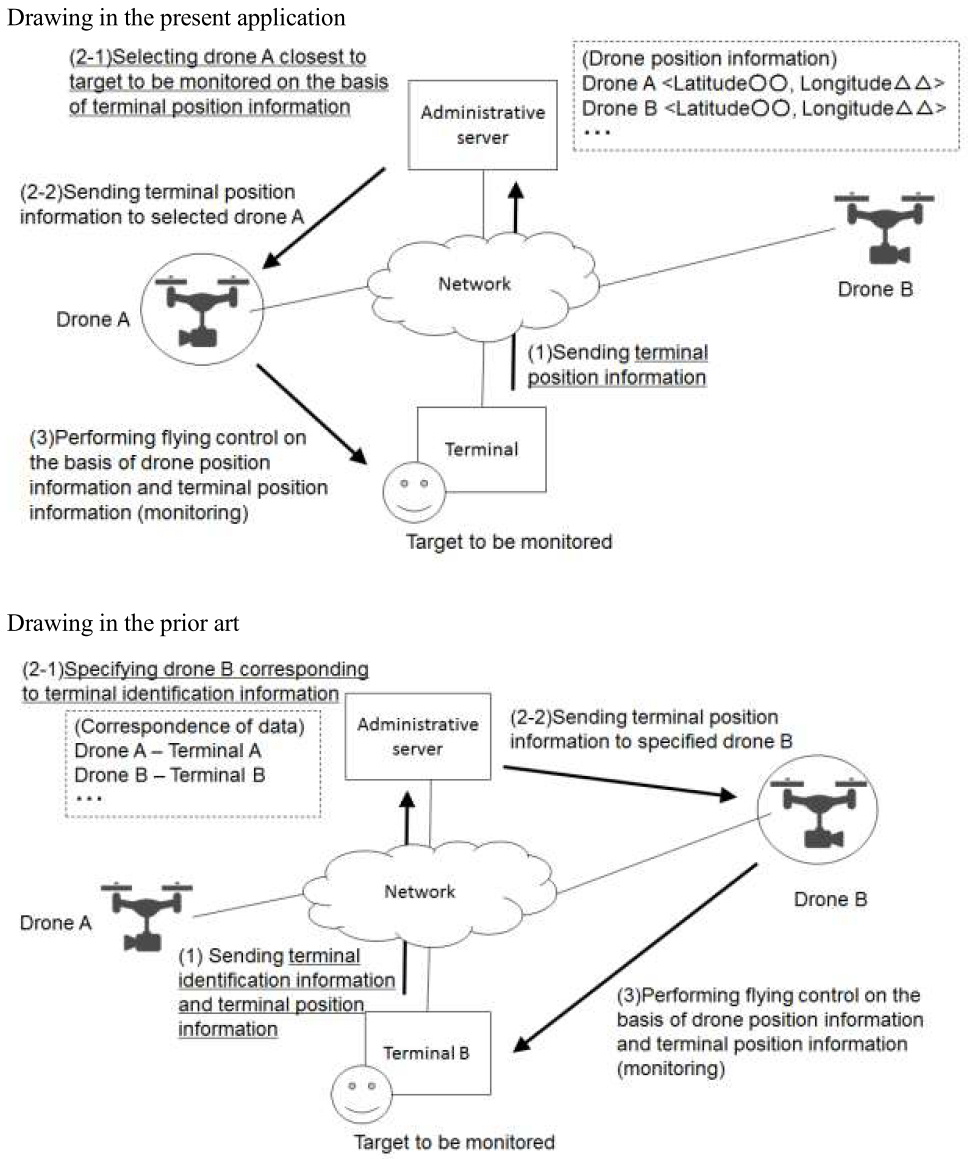
Overview of the description
The present invention relates to a drone monitoring system for monitoring children and elderly people by utilizing autonomously flying unmanned object (drone).
The drone monitoring system of the present invention comprises a plurality of drones, a terminal to be carried by a child or an elderly who is a target to be monitored, and an administrative server. The drone is equipped with image capturing means and various types of sensors, thereby detecting abnormality of the target to be monitored. The drone also comprises means for announcing abnormality to people near the target to be monitored, as required. Further, a plurality of drones is arranged in advance at positions of different terrain and is shared among users of the present system. Then, the administrative server stores position information of each drone.
An operation of the present system will be described below.
(1) The terminal acquires a current position of the terminal itself as terminal position information and continuously sends the information to the administrative server.
(2-1) The administrative server selects a drone closest to the target to be monitored on the basis of the received terminal position information.
(2-2) The administrative server continuously sends the terminal position information received from the terminal to the selected drone.
(3) The drone performs flying control of the drone itself on the basis of drone position information that the drone acquires as a current position of itself and a position of the target to be monitored that the drone continuously receives from the administrative server. More specifically, in order to monitor the target to be monitored in an appropriate way, the drone performs flying control such that the drone flies away from the target to be monitored by a fixed distance, keeps a constant height, and continues autonomous flight.
(2) Prior art
Title of Invention
...
[Claim 1] A healthcare system comprising a wearable sensor, a healthcare server, and a terminal device,
wherein the wearable sensor is a clothing type sensor that a wearer wears and comprises
means for measuring biological data containing a body temperature and heart rate of the wearer, and
means for sending the biological data to the terminal device;
wherein the terminal device comprises
means for receiving the biological data from the wearable sensor,
means for periodically summarizing the received biological data to send a result thereof to the healthcare server,
means for receiving a health index value A received from the healthcare server, and
means for displaying the health index value A on a screen; and
wherein the healthcare server comprises
means for calculating a health index value A of the wearer by analyzing the biological data received from the terminal device by means of analysis procedure Y, and means for sending the calculated health index value A to the terminal device.
Overview of the description
The present invention relates to a drone monitoring system for monitoring children and elderly people by utilizing autonomously flying unmanned object (drone).
The drone monitoring system of the present invention comprises a plurality of drones, a terminal to be carried by a child or an elderly who is a target to be monitored, and an administrative server. The drone is equipped with image capturing means and various types of sensors, thereby detecting abnormality of the target to be monitored. The drone also comprises means for announcing abnormality to people near the target to be monitored, as required. Further, the administrative server manages the drones in a manner that one drone is related to one corresponding terminal.
An operation of the present system will be described below.
(1) The terminal sends identification information of the terminal itself to the administrative server. Subsequently, the terminal acquires a current position of the terminal itself as terminal position information and continuously sends the information to the administrative server.
(2-1) The administrative server specifies a drone corresponding to the received terminal identification information.
(2-2) The administrative server continuously sends the terminal position information received from the terminal to the specified drone.
(3) The drone performs flying control of the drone itself on the basis of drone position information that the drone acquires as a current position of itself and a position of the target to be monitored that the drone continuously receives from the administrative server. More specifically, in order to monitor the target to be monitored in an appropriate way, the drone performs flying control such that the drone flies away from the target to be monitored by a fixed distance, keeps a constant height, and continues autonomous flight.
(3) Conclusion
The invention of Claim 1 has novelty.
The invention of Claim 2 lacks novelty.
[Explanation]
- Claim 1
The invention of Claim 1 differs from the invention disclosed in the cited document in a structure of “selecting a drone closest to the target to be monitored on the basis of the received terminal position information”.
That is, there is a difference between the invention of Claim 1 and the invention disclosed in the cited document. Therefore, the invention of Claim 1 has novelty.
- Claim 2
The invention of Claim 2 is directed to a “drone”. Claim 2 describes matters as to “administrative server” which is the other subcombination. That is, Claim 2 includes a description that “the administrative server comprises means for selecting a drone closest to the target to be monitored on the basis of the terminal position information received from the terminal of the target to be monitored and means for sending the terminal position information to the selected drone”.
However, how the administrative server selects a drone for monitoring a target to be monitored on the basis of what kind of standard will not affect a structure, a function, etc. of the drone of Claim 2. This means that the above matters of other subcombination do not specify the structure, the function, etc. of the drone.
When comparing the invention of Claim 2 with the invention disclosed in the cited document, there is a difference in description and expression in the matters of the other subcombination; however, there is no difference in a structure, a function, etc. There is no other difference between the invention of Claim 2 and the invention disclosed in the cited document. Therefore, the invention of Claim 2 lacks novelty.
3. Cases pertinent to Inventive Step
[Case 26] Supply Chain Management Method
Title of invention
Supply Chain Management Method
[Claim 1]
A computer implemented method for managing a supply chain, comprising the steps of:
receiving a demand for a product;
selecting at least one first source(s) to satisfy the said demand, based on information including operation status data at a plurality of sources of the said product, and generating a provisional reservation for a supply from the selected source(s);
determining whether there is a need for a requisition for any component part or material of the said product for the first source(s) to implement the said reservation;
selecting, where it is determined that there is a need for the said requisition, at least one second source(s), from among a plurality of sources of the component part or material, to satisfy the requisition as a demand, based on information including operation status data at the sources, and generating a provisional reservation for a supply from the selected source(s); and
updating the provisional reservations generated so far to confirmed reservations where, for each component part or material of the said product, it has been determined that the requisition is not necessary or the provisional reservation has been generated.
[Drawing in the present application]
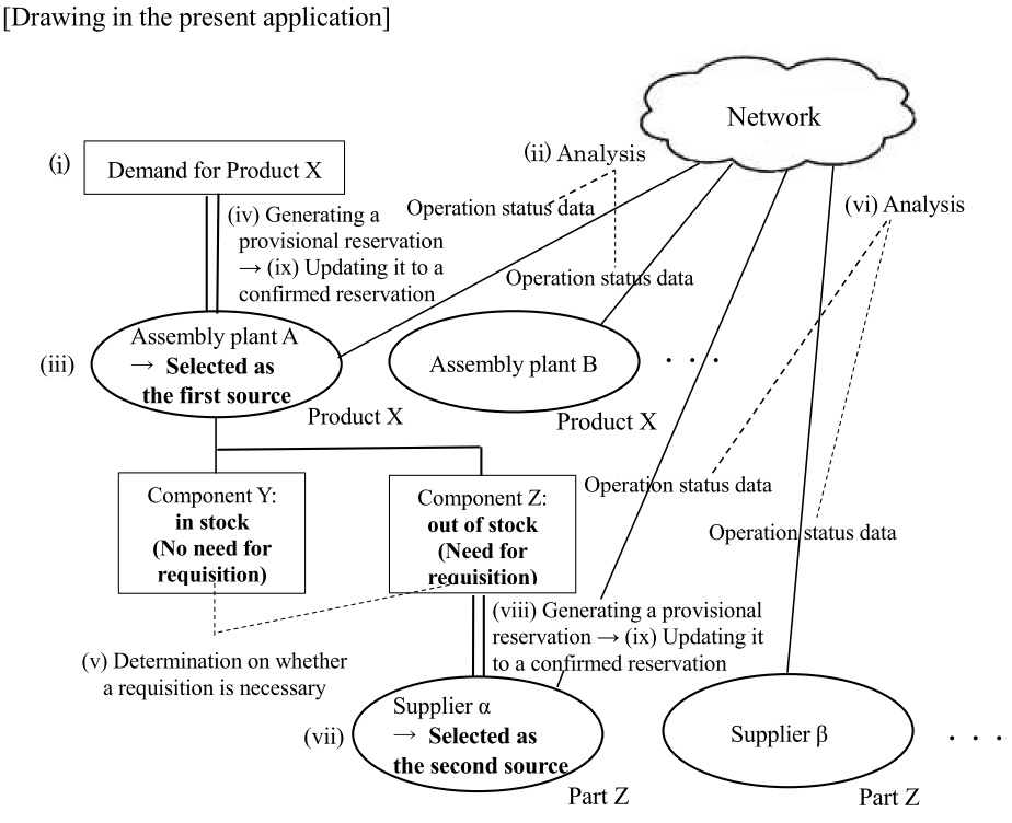
[Problem to be Solved by the Invention] The present invention addresses the problem, in relation to the supply chain management, of determining whether there is a need for a requisition for any component part or material of a product, and generating automatically by a computer a provisional reservation and a confirmed reservation in response to, inter alia, operational status at a supply source, where the requisition is necessary.
[Solution for the Problem to be solved] The method of the present invention selects at least one first source(s) to satisfy a demand for a product in a supply chain, based on information including operation status data at a plurality of sources of the product. The operation status data may include real-time data at a production facility of a supplier (as a supply source) such as machine tool operation data and the amount of works waiting for processing, and the operation status data are utilized through communication via a network such as the Internet. Analysis of the operation status data enables the selection of supply source(s) to reflect properly the supply capacity of each source moment by moment. Upon selection of at least one first source(s) to satisfy the demand, the method generates, at this stage, “provisional reservation(s)” for supply from the selected source(s).
Next, the method determines whether there is a need for a requisition for any component part or material of the product. Where it is determined that there is a need for the requisition, at least one second source(s) is/are selected, from among a plurality of sources of the component part or material, to satisfy the requisition as a demand, based on information including operation status data. Such a process is reiterated as necessary. Where, as a result, for each component part or material of the said product, it has been determined that the requisition is not necessary or otherwise the provisional reservation has been generated, the provisional reservations generated so far will be updated to confirmed reservations.
Accordingly, the method of the present invention is able to generate promptly provisional reservation(s) even in the case of a complicated supply chain with a number of tiers, and to find the status of insufficient supply in the supply chain, based on the existence of remaining provisional reservation(s) without being updated to confirmed reservation(s), if any.
- State of the art (Prior art, well-known art, etc.)
Cited invention 1 (Invention disclosed in the cited document 1 (D1)):
A computer implemented method for managing the supply and demand of a product, comprising the steps of:
receiving a demand for a product;
selecting a source to satisfy the said demand, based on information including operation status data at a plurality of sources of the said product;
determining whether the said demand is satisfied by the supply from the said source; and
selecting, where it is determined that the demand is not satisfied, another source to satisfy the unsatisfied demand, from among a plurality of sources of the said product, based on information including operation status data at the sources, or
generating, where it is determined that the demand is satisfied, reservations for supply from the sources selected so far.
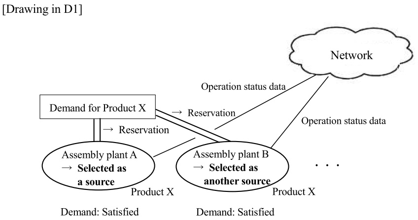
Cited invention 2 (Invention disclosed in the cited document 2 (D2)):
A computer implemented method for assisting the inventory management of parts at a production facility, comprising the steps of:
receiving a demand for a product;
identifying component parts necessary for manufacturing the said product;
determining whether the stock of each component part is sufficient to satisfy the said demand;
indicating, where it is determined that the stock is insufficient, possible source(s) of the said component part to satisfy the said demand and their supply capacity, based on information including operation status data at a plurality of sources of the said part, or
indicating, where it is determined that the stock is sufficient, information regarding the said stock.
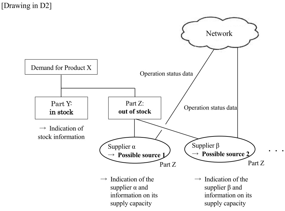
[Conclusion] The invention of Claim 1 involves an inventive step.
[Explanation]
(Considered motivation)
(1) Relation of technical fields
Both D1 and D2 are directed to the method regarding the supply and demand management of a product, and therefore each field of technology is mutually related.
(2) Similarity of problems to be solved
Both D1 and D2 address the same problem of providing a computer implemented method for the supply and demand management of a product, based on information including operation status data at a plurality of supply sources.
(Explanation on the non-existence of an inventive step objection)
The invention of Claim 1 differs from the cited invention 1 in the following aspects:
(Difference 1)
While Claim 1 recites a method for managing a supply chain comprising a step of determining whether there is a need for a requisition for any component part or material of a Demand for Product X Part Y: in stock Network Operation status data Part Z: out of stock → Indication of stock information Part Z Part Z → Indication of the supplier α and information on its supply capacity → Indication of the supplier β and information on its supply capacity ・・・ Operation status data Supplier α → Possible source 1 Supplier β → Possible source 2 product, for the selected source(s) to implement the supply of the product, wherein the method selects, where it is determined that there is a need for the said requisition for the component part or material, at least one second source(s), from among a plurality of sources of the component part or material, to satisfy the requisition as a demand, based on information including operation status data at the sources,
the cited invention 1 is a method for managing the supply and demand of a product and does not take into account a requisition for any component part or material of the product.
(Difference 2)
While the method of Claim 1 generates a “provisional reservation” for a supply from the selected source(s) and updates the “provisional reservations” generated so far to confirmed reservations where, for each component part or material of the said product, it has been determined that the requisition is not necessary or the “provisional reservation” has been generated,
the method of the cited invention 1 lacks features regarding the generation of a “provisional reservation” and the updating of such a “provisional reservation” to a confirmed reservation, although it generates reservations for supply from the selected sources.
First, analysis is made with regard to Difference 1.
Both D1 and D2 are directed to the method regarding the supply and demand management of a product, and therefore each field of technology is mutually related.
Furthermore, both D1 and D2 address the same problem of providing a computer implemented method for the supply and demand management of a product, based on information including operation status data at a plurality of supply sources.
In this light, it would have been obvious to one of ordinary skill in the art to apply D2 to D1, to take into account, further than the supply and demand management of a product itself, a requisition for a component part or material of the product for better supply and demand management, so as to manage a supply chain by incorporating in the method the steps of determining whether there is a need for a requisition for any component part of a product and selecting, where it is determined that there is a need for the requisition for the component part, at least one second source(s), from among a plurality of sources of the component part, to satisfy the requisition as a demand, based on information including operation status data at the sources.
Now, Difference 2 is considered.
D2, as well as D1, is silent about the features of Claim 1 regarding the generation of a “provisional reservation” and the updating of such a “provisional reservation” to a confirmed reservation.
The method of Claim 1 generates, upon the selection of one or more source(s) to satisfy the said demand for a product in the supply chain, a provisional reservation for a supply from the selected source(s), and then updates the generated provisional reservations to confirmed reservations where all the necessary provisional reservations for the supply chain have been generated. This enables the method of Claim 1 to generate promptly provisional reservation(s) even in the case of a complicated supply chain with a number of tiers, and to find the status of insufficient supply in the supply chain, based on the existence of remaining provisional reservation(s) without being updated to confirmed reservation(s), if any. The present functionality is considered to constitute an advantageous effect, which is not readily expected from D1 and D2.
As seen from the above analysis, the features of Claim 1 regarding the generation of a “provisional reservation” and the updating of such a “provisional reservation” to a confirmed reservation cannot be deemed to be design variation etc. (namely, design variation or design choice associated with an application of specific techniques to solve certain problems) practicable upon the application of D2 to D1.
Hence, Claim 1 recites features disclosed neither in D1 nor D2 with an advantageous effect not readily expected from D1 and D2, from which it is concluded that the claimed invention involves an inventive step over D1 and D2.
[Case 27] Running Supporting System
Title of Invention
Running Supporting System
What is claimed is:
[Claim 1] A running supporting system comprising a wrist watch type device having a screen interface and a GPS function, and an information distributing server communicative with the wrist watch type device through a network,
wherein the wrist watch type device has:
course information receiving means for receiving specification of course information from a user through the screen interface; and
transmitting means for transmitting the course information to the information distributing server, and continuously transmitting running information including position information and time information which are acquired by the GPS function to the information distributing server while the user performs the running,
the information distributing server has:
recording means for producing first lap time information corresponding to the course information based on the course information and the running information which are received from the wrist watch type device, and recording the resulting first lap time information in a running history database within the information distributing server;
acquiring means for acquiring a plurality of second lap time information previously recorded in the running history database, and corresponding to the course information; and
transmitting means for producing running support information which supports the running of the user based on comparison of the first lap time information with a plurality of second lap time information, and transmitting the resulting running support information to the wrist watch type device,
the wrist watch type device further has a displaying means for receiving the running support information from the information distributing server and displaying the running support information on the screen interface, and
the plurality of second lap time information is lap time information which is produced based on the newest running information transmitted from the wrist watch type device which a user different from the user has.
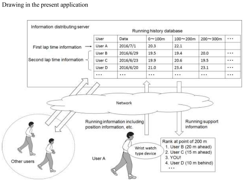
Overview of the description
[Background Art] There is a known user wearable wrist watch type device which presents comparison of his/her past running history with information on current running.
[Problem to be Solved by the Invention] However, when the user performed the running alone using the wrist watch type device concerned, since although reference could be made to the comparison with the past himself/herself, the sense of the competition with other persons could not be obtained. Therefore, it was difficult to keep the motivation of the running.
[Solution for the Problem to be Solved] The user performs the running while he/she wears the wrist watch type device including the screen interface and the GPS function (hereinafter referred to as “the device” in this section). The user manipulates the device before start of the running, and specifies a course along which he/she will perform the running from now. The information on the course thus specified and the user is transmitted to the information distributing server. The information distributing server recognizes that the user starts to perform the running along the specified course. During the running, the running information including both the position information and the time information of the user which are acquired by the GPS function is continuously transmitted from the device to the information distributing server.
In the information distributing server, the lap time information (first lap time information) for each predetermined distance interval of the user is produced based on the running information transmitted from the device, and stored in the running history database within the information distributing server. Here, the information distributing server holds the past lap time information on a plurality of users for each course in the running history database. It is to be noted that in the running history database, only up to one piece of the lap time information of the same user is stored with respect to the same course, and when new lap time information is produced with respect to the same user, the new lap time information is overwritten on the old lap time information.
The information distributing server produces running support information involving a virtual rank of the user, and virtual distances to other users by comparing the first lap time information with the past lap time information (second lap time information) on a plurality of other users stored in the running history database. The information distributing server transmits the running support information thus produced to the device of the user. Since the first lap time information is suitably updated when the running information transmitted from the device is stored, the running support information is also updated each time, and transmitted to the device.
In the device of the user, the running support information transmitted from the information distributing server is displayed on the screen interface.
[Effect of Invention] During the running, the user can refer to the running support information including the virtual rank of the user, and the virtual distances to other users on the wrist watch type device. Therefore, the user can obtain the sense of the competition with other users, and can hold the motivation of the running.
- State of the art (Prior art, well-known art, etc.)
Cited invention 1 (Invention disclosed in the cited document 1 (D1)):
A wrist watch type device having a screen interface and a GPS function, having:
course information receiving means for receiving specification of course information from a user through the screen interface;
recording means for producing first time information corresponding to the course information based on running information including position information and time information which are acquired by the GPS function while the user performs running, and recording the resulting first lap time information in a running history database within the wrist watch type device;
acquiring means for acquiring a plurality of second lap time information which is previously recorded in the running history database, and corresponds to the course information; and
displaying means for producing running support information which supports the running of the user by comparing the first lap time information with the second lap time information, and displaying the resulting running support information on the screen interface.
(Problem to be solved)
By presenting the information obtained based on the current lap time information, and the past lap time information recorded in the wrist watch type device as the running support information, the user can perform the running while he/she refers to the information on the comparison with the past lap time information of himself/herself.
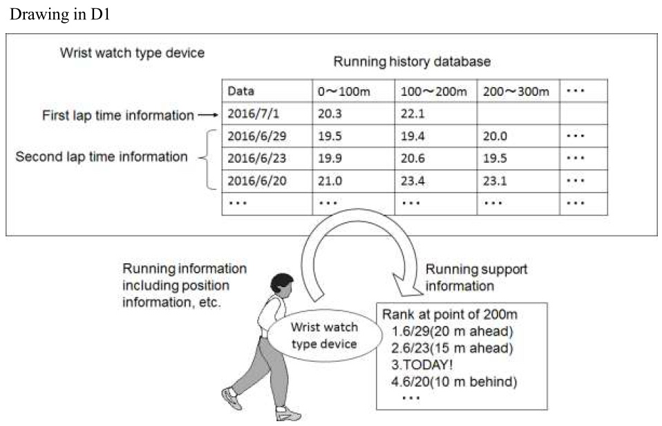
Well-known art:
The technique that in the system in which the server and the terminal can communicate with each other, due to the storage capacity, and the processing burden reduction on the terminal side, the data required at the terminal is transmitted to the server, the processing is executed based on the data concerned in the server, and the processing result is transmitted from the server to the terminal.
[Conclusion] The invention of Claim 1 involves an inventive step.
[Explanation]
(Considered motivation)
- Similarity of problems to be solved
Although the cited invention 1 does not describe the problem about the storage capacity and the processing load of the terminal, since the wrist watch type device of the cited invention 1 is also the terminal on the user side, it is an obvious problem to a person skilled in the art that there is a limit in the throughput and the storage capacity.
Therefore, the cited invention 1 and the well-known art are common in problem to each other.
(Explanation for no reason for refusal)
When the invention of Claim 1 is compared with the cited invention 1, both of them are different from each other in the following points.
(Difference 1)
A point that in the invention of Claim 1, which is a system comprising a wrist watch type device and an information distributing server, the running information acquired in the wrist watch type device is transmitted to the information distributing server, and in the information distributing server, the running support information is produced by comparing the first lap time information with a plurality of second lap time information, and transmitted to the wrist watch type device, whereas in the cited invention 1, which is a wrist type device, the comparison of the first lap time information with a plurality of lap time information, and the production of the running support information are performed in the wrist watch type device.
(Difference 2)
A point that in the invention of Claim 1, the second lap time information is produced based on the newest running information transmitted from the wrist watch type device which the user different from the user of the first lap time information has, whereas in the cited invention 1, with respect to the second lap time information, such specification is not performed.
The difference 1 will be examined.
The wrist watch type device of the cited invention 1 is the terminal on the user side, and thus it is an obvious problem to a person skilled in the art that there is a limit in the throughput and the storage capacity.
On the other hand, the technique with which in the system in which the server and the terminal can communicate with each other, due to the storage capacity and the processing load reduction on the terminal side, the data acquired in the terminal is transmitted to the server, the processing is executed based on the data concerned in the server, and the processing result is transmitted from the server to the terminal is known as the well-known art.
Therefore, a person skilled in the art could have easily conceived of applying the above well-known art, managing the running history database which the wrist watch type device has on the server side from a viewpoint of the storage capacity and the processing load, and the running information acquired in the wrist watch type device is transmitted to the information distributing server, and in the information distributing server, the running support information is produced by comparing the first lap time information with a plurality of second lap time information, and transmitted to the wrist watch type device.
The difference 2 will be examined.
The cited information 1 involves a problem that the running can be performed while the information on the comparison with the past lap time information on the user himself/herself is referred, and does not disclose the matter about the comparison with other users. In addition, that matter is not conceived easily by a person skilled in the art. From this reason, performing the comparison with the second lap time information based on the newest running information transmitted from the wrist watch type device which the different user has cannot be said a design variation, etc. (design variation or design choice associated with an application of specific techniques to solve certain problems) which may be performed when the well-known art is applied to the cited invention 1.
Moreover, the invention of Claim 1 has the advantageous effect, relative to the cited invention 1, that even when the user performs the running alone, he/she can obtain the sense of the competition with other users by producing the running support information based on the comparison with the lap time information of the different user.
In general consideration of the above circumferences, it could not be said that a person skilled in the art could have easily arrived at the invention of Claim 1 by applying the well-known art to the cited invention 1.
[Case 28] Heavy Rain Point Specifying System
Title of Invention
Heavy Rain Point Specifying System
What is claimed is:
[Claim 1] A heavy rain point specifying system comprising windshield wiper operation sensors attached to windshield wipers which a plurality of vehicles equip, and an analyzing server connected to the windshield wiper operation sensors through a network,
wherein the windshield wiper operation sensor comprises:
a detecting unit for detecting operation information including acceleration information of the windshield wiper;
an acquiring unit for acquiring current position information on the sensor; and
a transmitting unit for transmitting the current position information made to correspond to the operation information to the analyzing server,
the analyzing server comprises:
a collecting unit for collecting the operation information and the current position information from the plurality of windshield wiper operation sensors; and
an analyzing unit for statistically analyzing the current position information made to correspond to the operation information, exhibiting that the windshield wiper is operated at a high speed, of a plurality of collected operation information, thereby specifying a point at which heavy rain occurs.
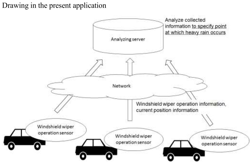
Overview of the description
[Problem to be Solved by the Invention] A technique for specifying a point at which heavy rain occurs in detail is desired.
[Solution for the Problem to be Solved] In order to specify the heavy rain point, the sensor attached to the windshield wiper which the vehicle includes is utilized. The sensor detects the operation information including the acceleration information of the windshield wiper, and transmits the operation information made to correspond to the current position information on the sensor to the analyzing sensor.
The analyzing server collects the operation information and the current position information from the sensors attached to the windshield wipers of a large number of vehicles. In addition, the analyzing server extracts the operation information concerned to only the operation information representing that the windshield wiper is operated at a given speed or more, and analyzes the current position information made to correspond to the operation information obtained by the limitation, thereby specifying the point at which the heavy rain occurs. Specifically, the geographical space is divided into meshes each having a particular distance square, and when the number of current position information corresponding to the extracted operation information included in a certain mesh is a given number or more, the mesh concerned is specified as the heavy rain occurring point.
- State of the art (Prior art, well-known art, etc.)
Cited invention 1 (Invention disclosed in the cited document 1 (D1)):
A windshield wiper failure detecting system comprising windshield wiper operation sensors attached to windshield wipers which a plurality of vehicles equips, and an analyzing server connected to the windshield wiper operation sensors through a network,
wherein the windshield wiper operation sensor comprises:
a detecting unit for detecting operation information including acceleration information of the windshield wiper;
an acquiring unit for acquiring current position information on the sensor; and
a transmitting unit for transmitting the operation information with the current position information being made to correspond to the operation information to the analyzing server,
the analyzing server comprises:
a collecting unit for collecting the operation information from the plurality of windshield wiper operation sensors;
an analyzing unit for specifying the windshield wiper in which a failure was caused based on comparison of the collected operation information with the past operation information having the failure; and
a notifying unit for notifying an administrator of the specified windshield wiper, and current position information thereof.
(Problem to be solved)
To collect the operation information on the windshield wipers from the windshield wiper operation sensors attached to the vehicles, and specify the windshield wiper in which the failure is caused based on the comparison with the past failure history.
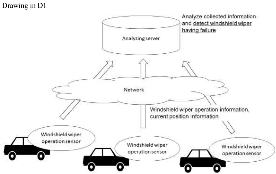
Cited invention 2 (Invention disclosed in the cited document 2 (D2)):
A heavy rain point specifying system comprising a plurality of portable terminals, and an analyzing server connected to the plurality of portable terminals through a network,
wherein the portable terminal comprises:
a receiving unit for receiving an input of a message to the network by a user;
an acquiring unit for acquiring current position information on the terminal; and
a transmitting unit for transmitting the message and the current position information to the analyzing server,
the analyzing server comprises:
a collecting unit for collecting the messages and current position information from the plurality of portable terminals; and
an analyzing unit for statistically analyzing the current position information correspond to the message including words about the heavy rain of the plurality of messages collected, thereby specifying a point at which the heavy rain occurs.
(Problem to be solved)
To statistically analyze the messages, including the position information, which are posted on a Social Networking Service (SNS) from the portable terminals of the users, thereby specifying the point at which the heavy rain occurs.

(Supplementary explanation)
The cited invention 2 limits the collected messages to the message including the words about the heavy rain, and analyzes the current position information made to correspond to the message obtained through the limitation, thereby specifying the heavy rain point. Specifically, the geographical space is divided into meshes each having a particular distance square, and when the number of current position information corresponding to the limited messages included in a certain mesh is a given number or more, the mesh concerned is specified as the heavy rain occurring point.
In addition, it is the common general knowledge that in the point at which the heavy rain occurs, a large number of vehicles operates the windshield wipers at the high speeds.
[Conclusion] The invention of Claim 1 involves an inventive step.
[Explanation]
(Considered motivation)
(1) Relation of technical fields
Since the cited invention 1 is the invention relating to the detection of the failure of the windshield wiper, and the cited invention 2 is the invention relating to the specification of the heavy rain point using the message, they are different in technical field from each other.
(2) Similarity of problems to be solved
The cited invention 1 involves the problem that the operation information on the windshield wipers is collected, and the windshield wiper in which the failure is caused is specified by the comparison with the past failure history. On the other hand, the cited invention 2 involves the problem that the heavy rain point is specified by utilizing the messages including the words about the heavy rain. Therefore, the problems of the both are different from each other.
(3) Similarity of operations or functions
The cited invention 1 compares the collected operation information on the windshield wipers with the past operation information, whereas the cited invention 2 statistically analyzes the messages including the position information, thereby specifying the heavy rain point. Therefore, they are different in operations and functions from each other.
(Explanation for no reason for refusal)
When the invention of Claim 1 is compared with the cited invention 1, both of them are different in following point from each other.
(Difference)
A point that in the invention of Claim 1, the analyzing server statistically analyzes the current position information which is made to correspond to the operation information and which indicates that the windshield wipers are operated at the high speeds of a plurality of collected operation information, thereby specifying the point at which the heavy rain occurs, whereas in the cited invention 1, the analyzing server specifies the windshield wiper in which the failure is caused based on the comparison of the collected operation information with the past operation information on the windshield wiper in which a failure was caused.
(Motivation)
In the failure detecting system of the cited invention 1, the cited invention 2 is applied, the common general knowledge is taken into consideration, and the position information made to correspond to the operation information indicating that the windshield wiper is operated at the high speed is analyzed, thereby examining whether or not a person skilled in the art could easily conceive of specifying the heavy rain point.
When up to (1) to (3) of the considered motivation are comprehensively taken into consideration, it is not said that there is the motivation in which the cited invention 2 is applied to the cited invention 1.
In the light of the above circumstances, it is impossible to say that a person skilled in the art could have easily conceived of configuring the invention of Claim 1 by applying the cited invention 2 to the cited invention 1, and taking the common general knowledge into consideration.
[Case 29] Medical Device Maintenance Server
Title of Invention
Medical Device Maintenance Server
What is claimed is:
[Claim 1] A medical device maintenance server for producing a maintenance plan pertaining to implementation of maintenance for a plurality of medical devices which a business operator possesses, having:
a collecting unit for collecting information on an operation status of a medical device, collected from a sensor mounted to the medical device through a network, and recording the operation status in an operation status storing unit;
an analyzing unit for calculating degrees of deterioration of consumables which the medical device includes by analyzing the operation status recorded in the operation status storing unit, and recoding the degrees of deterioration in a consumables status storing unit;
a medical device information database for storing information on a business operation, and information on the medical devices which the business operator possesses correspond to each other; and
a planning unit for producing a maintenance plan in which timing of the maintenance for a plurality of medical devices, and information on a consumables as an object of exchange are summarized for every business operator based on the degrees of deterioration of the consumables recorded in the consumables status storing unit, and the information recorded in the medical device information database, and recording the maintenance plan in a maintenance plan storing unit.

Overview of the description
[Background Art] How efficiently the maintenance of the medical devices possessed is performed was the important problem for the business operators of medical institutions, etc. Heretofore, there has been known the technique of collecting the data on the operation status of the medical device from the sensors mounted to the medical device, and analyzing the collected data, thereby estimating the deterioration status of the consumables which the medical device includes, and the medical device is notified of the maintenance deadline within which the maintenance is suitably performed before the medical device gets out of order.
[Problem to be Solved by the Invention] However, the business operator possesses a large number of medical devices in many cases, and thus it is complicated to manage the maintenance deadline of all the medical devices. Then, it is desirable for the business operator to receive the maintenance plan in which the information on the maintenance for all the medical devices which he/she possesses is gathered.
[Solution for the Problem to be Solved] In the present invention, the maintenance plan about the medical devices which the business operator possesses is produced for every business operator based on the data, on the operation status of the medical devices, which is collected from the sensors mounted to each of the medical devices, and the information on the medical devices which the business operator possesses.
A concrete embodiment will be described.
The business operator possesses a plurality of kinds of medical devices such as an MRI, and the various sensors are mounted to each of the medical devices. The medical device maintenance server collects the data, on the operation status of the medical devices, which the sensors acquire through the network, and stores the collected data as the operation status data on the operation status storing unit.
The medical device maintenance server includes the medical device information database in which the information on the business operator, and the information on the medical devices which the business operator possesses are made to correspond to each other.
In addition, the medical device maintenance server calculates the degree of deterioration of the consumables which the medical devices include by analyzing the collected operation status data, and records the degree of deterioration of the consumables in the consumables status storing unit. The known technique is use for the method of calculating the degree of deterioration of the consumables from the operation status data on the medical devices.
Subsequently, a planning unit produces the maintenance plan including the timing of the maintenance of the possessed medical devices, and the information on the consumables as the object of the exchange for every business operator based on the degree of deterioration of the consumables, recorded in the consumables status storing unit, and the information recorded in the medical device information database, and records the resulting maintenance plan in the maintenance plan storing unit. The maintenance plan includes the information on when the next maintenance will be performed, and in this case, which consumables of which medical device possessed by the business operator should be exchanged, and the consumables whose exchange time is approaching are collectively exchanged at the same timing, and so forth. Thus, the maintenance plan is produced so that the maintenance efficient for the business operator can be performed.
The maintenance plan thus produced is provided from the medical device maintenance server to the business operator. The business operator requests the maintenance operator to carry out the maintenance plan as it is, or to carry out the maintenance plan after suitably carrying out a change thereof.
[Effect of Invention] The present invention produces the maintenance plan including the information on the maintenance timing and consumables as the object of the exchange of a plurality of medical devices possessed by the business operator for each of the business operators based on the operation status data, on the medical devices collected from the sensors, and provide the resulting maintenance plan to the business operator. Therefore, for the business operator who possesses a large number of medical devices, the burden exerted on the examination about the plan of the maintenance is reduced.
(Supplementary explanation)
Information processing for producing the maintenance plan for every business operator at the planning unit is concretely described using flowchart, etc. in the description and drawings.
- State of the art (Prior art, well-known art, etc.)
Cited invention 1 (Invention disclosed in the cited document 1 (D1)):
A medical device maintenance server for judging necessity of maintenance of a specific medical device, having:
a collecting unit for collecting information, on an operation status of a medical device, collected from sensors mounted to the medical device through a network, and recording the information on the operation status in an operation status storing unit;
an analyzing unit for calculating degrees of deterioration of a plurality of consumables which the medical device includes by analyzing the operation status recorded in the operation status storing unit, and recording the degrees of deterioration in a consumables status storing unit; and
a producing unit for producing maintenance information including information on a deadline of the maintenance of the medical device, and the consumables as an object of exchange based on the degree of deterioration, of the consumables, recorded in the consumables status storing unit, and recording the resulting maintenance information in a maintenance information storing unit.
(Problem to be solved)
To estimate the deterioration status of the consumables consisting the medical device based on the information collected from the sensors mounted to the medical device, and determine the deadline of the maintenance which should be implemented before the medical device gets out of order based on the estimation.
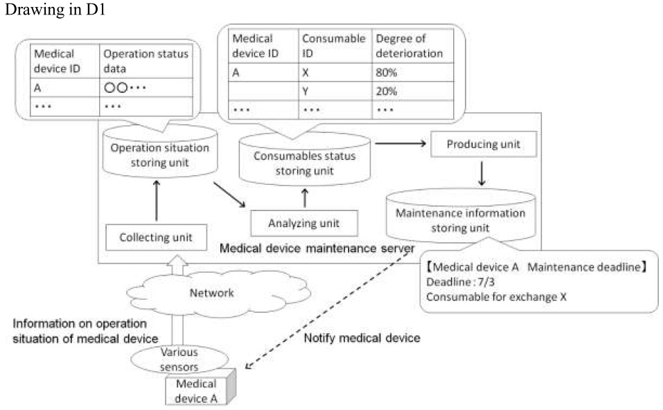
[Conclusion] The invention of Claim 1 involves an inventive step.
[Explanation] (Explanation for no reason for refusal)
When the invention of Claim 1 is compared with the cited invention 1, both of them are different in following point from each other.
(Difference)
In the invention of Claim 1, the medical device maintenance server has the medical device information database in which the information on the business operator is made to correspond to the information on the medical devices which the business operator possesses, and the maintenance plan is produced for every business operator which has plurality of medical devices, whereas the cited invention 1 produces the maintenance information on the specific medical device, but does not produce the maintenance plan for each business operator which has plurality of medical devices.
The above difference will be examined.
The cited invention 1 involves the problem that the deadline of the maintenance which should be implemented before the medical device gets out of order is determined. In addition, producing the maintenance plan for each business operator is different from the problem of cited invention 1 and also is not conceived easily by a person skilled in the art. Therefore, it cannot be said as a design variation, etc. (design variation or design choice associated with an application of specific techniques to solve certain problems) from the cited invention 1 to have the medical device information database in which the information on the business operator is made to correspond to the information on the medical devices which the business operator concerned possesses, and produce the maintenance plan summarized for every business operator.
Moreover, the invention of Claim 1 has the effect, advantageous relative to the cited invention 1, that the invention of Claim 1 has the matter pertaining to the difference, thereby reducing the burden of the consideration about the plan of the maintenance for the business operator who possesses a large number of medical devices.
Comprehensively assessing of the above circumstances, it cannot be said that a person skilled in the art would not have easily conceived of configuring the invention of Claim 1 based on the cited invention 1.
[Case 30] Construction Machine Maintenance Server
Title of Invention
Construction Machine Maintenance Server
What is claimed is:
[Claim 1] A construction machine maintenance server, having:
a collecting unit for collecting operation status data on a construction machine from sensors mounted to the construction machine through a network, and recording the operation status data in an operation status storing unit;
a judging unit for judging that maintenance of the construction machine is necessary when it is detected that a specific abnormality portent pattern is included in the collected operation status data;
an estimating unit for estimating consumables which are necessary for exchange by applying an estimation model which is created through machine learning to the operation status data for a predetermined period of time when the maintenance of the construction machine is necessary; and
an updating unit for receiving an input of information on the consumables which are actually exchanged at the time of a maintenance work, and updating the estimation model based on information.
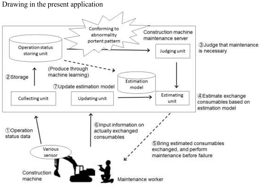
Overview of the description
[Background Art] There was a technique by which the failure is detected in advance, and the maintenance is performed before the actual failure occurs by collecting the operation status data on a construction machine, and analyzing the operation status data.
[Problem to be Solved by the Invention] It is important to reduce a total cost of maintenance by conducting inspections or maintenances of construction machines efficiently and effectively. In the maintenance of the construction machine, a plurality of consumables composing the construction machine needed to be exchanged. In particular, for the construction machine including a large number of consumables, a maintenance worker did not understand which consumables should be exchanged until the maintenance worker performed the actual maintenance work. Thus, the previous preparation was complicated.
[Solution for the Problem to be Solved] Means for detecting failures of a construction machine in advance, and estimating and providing information on the consumables which should be exchanged at the time of the maintenance.
A plurality of various sensors are mounted to the construction machine requiring maintenance. The various sensors transmit the operation status data as information on the operation status of the construction machine concerned to the construction machine maintenance server through the network. As for the operation status data, there is the various data on the operation, the operation time, the power consumption, the temperature, the vibration, and the like of the construction machine.
The construction machine maintenance server previously holds the specific abnormality portent pattern for the previous detection of the failure. In addition, when discovering the pattern conforming to the abnormality portent pattern in the collected operation status data, the judging unit judges that the maintenance of the construction machine is necessary.
When the judgement is made, an estimating unit estimates the consumables necessary for the exchange by applying the estimation model to the operation status data on the construction machine for which the judgement is made. Based on the estimation model, in response to the input of operation status data on the construction machine, data on the consumables estimated to be necessary for the exchange is outputted. Operation status data on the construction machine, when it is judged that the maintenance is required, and the history data on the consumables which are actually exchanged are subjected to the machine learning, thereby producing the estimation model.
Moreover, whenever the exchange of the consumables is performed, information on the actually exchanged consumables is received as the feedback to the estimation model. Therefore, the maintenance work is repetitively performed, thereby enhancing the precision of the estimation.
Furthermore, a report on the operation status based on the analysis of the operation status data on the construction machine is produced and provided to the users of the construction machine. The report includes log information of the operation status of the construction machine, guidance on usage and preventive measures against the failure for the user.
[Effect of Invention] According to the invention of the present application, failures of the construction machine can be detected in advance, and information on the consumables necessary for the exchange at the time of the maintenance can be estimated and provided to the maintenance worker.
(Supplementary explanation)
Information processing for producing the estimation model at the estimating unit is concretely described using flowchart, etc. in the description and drawings.
- State of the art (Prior art, well-known art, etc.)
Cited invention 1 (Invention disclosed in the cited document 1 (D1)):
A construction machine maintenance server, having:
a collecting unit for collecting operation status data on a construction machine from sensors mounted to the construction machine through a network, and recording the operation status data in an operation status storing unit;
an estimating unit for estimating consumables necessary to be exchanged by applying an estimation model created through machine learning for the operation status data for a predetermined period of time when maintenance of the construction machine is necessary; and
an updating unit for receiving an input of information on the consumables which are actually exchanged at the time of maintenance work, and updating the estimation model based on information.
(Problem to be solved)
To promote the convenience for a maintenance worker by estimating the consumables necessary to be exchanged by using the estimation model in the maintenance which is to be performed before the failure occurs in the construction machine.
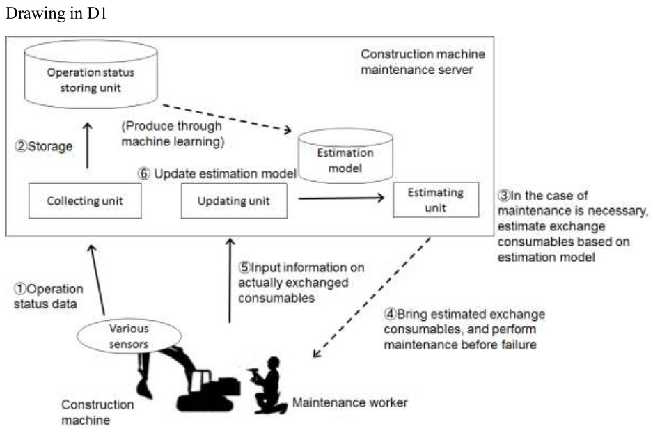
Cited invention 2 (Invention disclosed in the cited document 2 (D2)):
A server which collects operation status data on a construction machine from sensors mounted to the construction machine through a network; records the operation status data in a storing unit; judges that maintenance of the construction machine is necessary when it is detected that a specific abnormality portent pattern is included in the collected operation status data; and notifies the specific person of that.
(Problem to be solved)
To detect the portent of the failure through monitoring the operation status data on the construction machine, and perform the maintenance before the failure actually occurs.
[Conclusion] The invention of Claim 1 lacks an inventive step.
[Overview of Reason for Refusal] When the invention of Claim 1 is compared with the cited invention 1, both of them are different in following point from each other.
(Differences)
The invention of Claim 1 has a judging unit for judging that maintenance of the construction machine is necessary when it is detected that a specific abnormality portent pattern is included in the collected operation status data, whereas the cited invention 1 does not have the judging unit.
The above difference will be examined.
The cited invention 2, as described above, is the server which collects operation status data on a construction machine from sensors mounted to the construction machine through a network; records the operation status data in a storing unit; judges that maintenance of the construction machine is necessary when it is detected that a specific abnormality portent pattern is included in the collected operation status data; and notifies the specific person of that. Thus, D2 describes the method for performing the judgment by detecting the specific abnormality portent pattern within the operation status data as the method for judging the necessity for the maintenance of the construction machine.
Both the cited invention 1 and the cited invention 2 relate to the maintenance of the construction machine, and thus they are common in technical field to each other. In addition, both the inventions have the common problem in that the maintenance of the construction machine is suitably performed before the actual failure occurs. Moreover, both the inventions collect and analyze the operation status data on the construction machine, thereby outputting information for the maintenance of the constitution machine. Thus both the inventions have the common function.
When the above circumstances are comprehensively assessed, a person skilled in the art could have easily conceived of having a judgement unit for judging that the maintenance of the construction machine is necessary when it is detected that the specific abnormality portent pattern is included in the operation status data by applying the cited invention 2 to the cited invention 1.
[Explanation]
(Considered motivation)
(1) Relation of technical fields
The cited invention 1 and the cited invention 2 have the common technical fields in that the maintenance of the construction machine is performed.
(2) Similarity of problems to be solved
The cited invention 1 and the cited invention 2 have the common problem in that the maintenance of the construction machine is appropriately performed before the actual failure is generated.
(3) Similarity of functions
The cited invention 1 and the cited invention 2 are common in function to each other in that the operation status data on the construction machine is collected from sensors and analyzed, thereby outputting information for the maintenance of the construction machine.
[Measures of the applicant] In Claim 1, by adding “providing unit for producing a report on the operation status based on the analysis of the operation status data on the construction machine and providing the report to the users of the construction machine”, the above reason for refusal is overcome.
[Case 31] Learning System Comprising On-vehicle Devices and a Server
Title of Invention
Learning System Comprising On-vehicle Devices and a Server
What is claimed is:
[Claim 1] A learning system comprising a plurality of on-vehicle devices mounted on a plurality of vehicles respectively and a server that communicates with the said plurality of on-vehicle devices via a network,
wherein the said plurality of on-vehicle devices is comprised of:
an image recognition unit that executes image recognition, based on specific parameters, using image data around the vehicle taken by an on-vehicle camera;
a provision unit that provides the said server with the image data used for the said image recognition as data for learning;
an acquisition unit that acquires data to update the said parameters provided from the said server; and
an updating unit that updates the said parameters based on the said acquired data,
wherein, the said server is comprised of:
an acquisition unit that acquires the said data for learning provided from the said plurality of on-vehicle devices:
a learning unit that carries out machine learning based on the said data for learning and generates data for updating the said parameters; and
a provision unit that provides the said plurality of on-vehicle devices with the said data for updating.
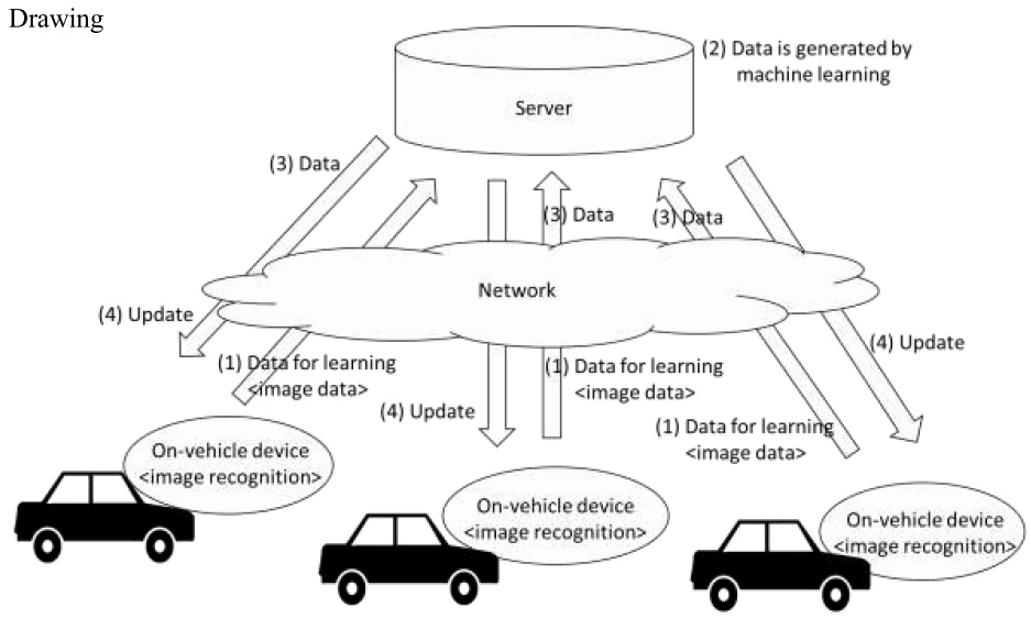
Overview of the description
[Background Art] An on-vehicle device performs image recognition to recognize vehicles, pedestrians and white lines drawn on roads around own vehicle.
[Problems to be solved by the invention] In the development stage of these on-vehicle devices, it has been tried to improve image recognition performance by machine learning. However, after products are shipped, no effort for improving image recognition performance has been made.
The present invention has been conceived in view of the above problem and aims to provide a learning system that allows image recognition performance to be improved after the on-vehicle devices are shipped.
[Solution for the Problem to be solved] An on-vehicle device is equipped with an image recognition unit and performs image recognition of vehicles, pedestrians and white lines drawn on roads around the vehicle based on image data around the vehicle taken by an on-vehicle camera. Image recognition is performed by algorithms such as support vector machines and neural networks that have specific parameters. Weights of these support vector machines and neural networks are updated by machine learning described later.
The on-vehicle device is equipped with a provision unit that, when it performs image recognition, provides a server with image data used for the image recognition as data for learning via a network. The frequency of provision can be set by a person skilled in the art as appropriate. The on-vehicle device provides image data, for example, every time when a certain amount of image data is accumulated.
On the other hand, the server is equipped with an acquisition unit and a learning unit that acquire data for learning provided from a plurality of the on-vehicle devices, perform machine learning to improve image recognition performance based on the data for learning and generate data to update parameters for image recognition. Machine learning is performed by means of unsupervised learning or supervised learning. In the case of unsupervised learning, a large amount of data collected from the on-vehicle devices (unsupervised data) is used to learn unsupervised features. Features refer to expressions that can express unsupervised data in the best mode (for example, linear combination of image pixels). In the case of supervised learning, it is necessary to create supervised data corresponding to each data for learning (for example, labels indicating the existence of pedestrians and the positions of white lines recognized by image recognition). Such work is carried out by operators who operate the server.
The server is equipped with a provision unit to provide each of the on-vehicle devices with data to update the said parameters via the network. The frequency of provision can be set by a person skilled in the art as appropriate. The server provides data on a regular basis, for example every week or every month.
The on-vehicle device is equipped with an acquisition unit and an updating unit to acquire data for parameters provided from the server, update parameters for image recognition based on the data and perform image recognition based on updated parameters.
Moreover, the provision unit of the on-vehicle device may generate data indicating running conditions of own vehicle such as the vehicle’s speed, steering angle and turn signal control as data on running conditions and provide the server with the data on running conditions when image recognition is performed together with image data as data for learning.
In this case, the learning unit of the server classifies data for learning based on the data on running conditions and generates data for updating parameters by performing machine learning depending on each running condition. By this way, high-precision image recognition is realized in accordance with running conditions. Specifically, when the vehicle is running at high speed, changes in positions of vehicles and pedestrians therearound (principally changes in positions in image in the vertical directions) become large among images taken continuously compared to the time when the vehicle is running at low speed. Similarly, when a steering angle is large, that is, a vehicle is turning around, changes in positions of vehicles and pedestrians therearound (principally changes in positions in image in the lateral directions) become large among images taken continuously compared to the time when a vehicle is running straight. Furthermore, when a turn signal is controlled during high-speed running, that is, a vehicle is changing a driving lane, changes in positions of white lines become large among images taken continuously. Therefore, it is not appropriate to perform uniform image recognition without taking into account running conditions such as that the vehicle is running at high speed or low speed, turning around or running straight and/or changing a driving lane. In the present invention, in order to realize high-precision image recognition depending on running conditions, the learning unit of the server carries out the machine learning and generates data for updating parameters depending on each running condition while the acquisition unit of the on-vehicle device acquires the data and the updating unit updates parameters based on the data.
As described above, machine learning depending on each running condition has a particularly-advantageous effect in a system comprising a plurality of on-vehicle devices and a server compared to a system that performs machine learning in one on-vehicle device. That is, in the system comprising a plurality of on-vehicle devices and a server, a large amount of data for learning is provided to the server, and sufficient data for learning exists even when it is classified for each running condition. Therefore, in order to realize high-precision image recognition even in a rare running condition for some vehicles, for example, in a running condition that a vehicle that does not usually run on a highway actually runs on a highway and changes a driving lane, such a system can appropriately update parameters of image recognition parameters by means of effective machine learning.
- State of the art (Prior art, well-known art, etc.)
Cited invention 1 (Invention disclosed in the cited document 1 (D1)):
A learning system comprising an on-vehicle device mounted on a vehicle,
wherein the on-vehicle device is comprised of:
an image recognition unit that executes image recognition, based on specific parameters, using image data around the vehicle taken by an on-vehicle camera;
a provision unit that provides image data used for the said image recognition as data for learning;
an acquisition unit that acquires the said data for learning provided;
a learning unit that performs machine learning based on the said data for learning to update the said parameters;
a provision unit that provides data to update the said parameters;
an acquisition unit that acquires data to update the said parameters;
an updating unit that updates the said parameters based on the said acquired data.
(Problems to be solved)
Image recognition performance is improved by updating parameters used for executing image recognition, after on-vehicle devices are shipped.
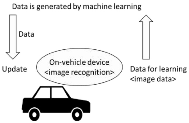
Well-known art:
For improving functions of various terminals including mobile type terminals,
a server generates data for updating the computer programs or the setting values of the computer programs collectively and provides a plurality of terminals therewith by making an analysis based on data that were used for processing of the programs and were provided from the plurality of terminal devices to the server via a network.
(Problems to be solved)
Functions of computer programs are improved after terminals are shipped.
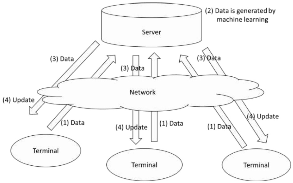
[Conclusion] The invention of Claim 1 lacks an inventive step.
[Overview of Reason for Refusal]
- Claim 1
When the invention of Claim 1 and the cited invention 1 are compared, they are different in the following point.
(Difference)
The invention of Claim 1 is a learning system comprising a plurality of on-vehicle devices mounted on a plurality of vehicles respectively and a server that communicates with the said plurality of on-vehicle devices via a network, wherein, the said plurality of on-vehicle devices are comprised of a provision unit that provides the said server with data for learning and an acquisition unit that acquires data for updating parameters provided from the said server, and the said server is comprised of an acquisition unit that acquires data for learning provided from the said plurality of on-vehicle devices, a learning unit that carries out machine learning based on the said data for learning and generates data for updating the said parameters and a provision unit that provides the said plurality of on-vehicle devices with the said data for updating. On the other hand, the cited invention 1 is a learning system comprising an on-vehicle device, wherein, the said on-vehicle device is comprised of a learning unit that carries out machine learning based on data for learning and generates data for updating parameters, but the on-vehicle device is not a plurality of vehicles that are mounted on a plurality of vehicles respectively and the said on-vehicle device and a server are not comprised of a provision unit and an acquisition unit to provide data each other and acquire data.
The above difference is now considered.
It is a well-known art that, for improving functions of various terminals including mobile type terminals, a server generates data for updating the computer programs or the setting values of the computer programs collectively and provides a plurality of terminals therewith by making an analysis based on data that were used for processing of the programs and were provided from the plurality of terminal devices to the server via a network.
The cited invention 1 and the well-known art have a common problem to be solved in that processing performance and functions of the computer software are improved after mobile-type devices on which the computer software is installed are shipped. Moreover, they have a common function that they generate data for updating the computer software based on data used for the processing thereof and update it based on the said generated data.
When the above-mentioned circumstances are considered comprehensively, a person skilled in the art could have easily conceived of applying the well-known art to the cited invention 1 and conceived of a configuration of the learning system comprising a plurality of on-vehicle devices mounted on a plurality of vehicles respectively and a server that communicates with the said plurality of on-vehicle devices via a network, wherein, the said plurality of on-vehicle devices are comprised of a provision unit that provides the said server with data for learning and an acquisition unit that acquires data for updating parameters provided from the said server, and the said server is comprised of an acquisition unit that acquires data for learning provided from the said plurality of on-vehicle devices, a learning unit that carries out machine learning based on the said data for learning and generates data for updating the said parameters and a provision unit that provides the said plurality of on-vehicle devices with the said data for updating.
Furthermore, an effect of the invention of Claim 1 that the image recognition performance can be improved after shipment is also to the extent that a person skilled in the art can predict.
[Explanation]
(Considered motivation)
(1) Similarity of problems to be solved
The cited invention 1 and the well-known art have a common problem to be solved in that processing performance and functions of the computer software are improved after mobile-type devices on which the computer software is installed are shipped.
(3) Similarity of functions
The cited invention 1 and the well-known art have a common function that they generate data for updating the computer software based on data used for the processing thereof and update it based on the said generated data.
[Measures of the applicant] In Claim 1, the applicant makes an amendment to add the following points: the provision unit of the on-vehicle devices provides the server with data on running conditions together with image data as data for learning, and the learning unit of the server classifies data for learning into a plurality of groups based on the said data on running conditions, carries out machine learning and generates data for updating parameters depending on each running condition.
In addition, the applicant argues in the written opinion that high-precision image recognition can be realized depending on running conditions such as that a vehicle is at high speed or low speed, turning around or running straight and/or changing a driving lane, even in a rare running condition for some vehicles, for example, in a running condition that a vehicle that does not usually run on a highway actually runs on a highway and changes a driving lane.
By these measures, the above reasons for refusal are overcome.
[Case 32] Quality management program of manufacturing lines
Title of Invention
Quality management program of manufacturing lines
What is claimed is:
[Claim 1] A quality management program of manufacturing lines causing a computer to realize:
a function of receiving data on inspection results of products that went through predetermined manufacturing processes and were inspected with regard to each of predetermined inspection items from inspection devices via a network and of storing it in a database;
a function of receiving data on manufacturing conditions when the products were manufactured from manufacturing devices via a network and of storing it in the said database after associating it with the said data on inspection results;
a function of training a neural network by means of deep learning about a relationship between inspection results of the said data on inspection results stored in the said database and manufacturing conditions that caused non-conformity among the said data on manufacturing conditions;
a function of monitoring test results data stored in the said database; and
a function of estimating manufacturing conditions that caused the non-conformity using the said trained neural network when the non-conforming test result is found as a result of the said monitoring.

Overview of the description
[Background Art] Quality management of products in manufacturing lines of a variety of products is performed by sampling data of a small number of products from a large number of products manufactured and examine a relationship between their manufacturing conditions and their quality based on overall distribution and a degree of variations of sampled data of a small number of products. Currently, technologies such as monitoring network database have progressed so that it is relatively easy to integrally accumulate data on manufacturing conditions and inspection results of all products that have gone through manufacturing lines using barcodes or another type of data.
[Problems to be solved by the invention] Though it will become possible to perform more advanced quality management by effectively using an enormous quantity of data on manufacturing histories, the data processing capabilities of humans are limited. Moreover, an analysis of non-conforming using detailed data relies largely on judgment or hunch of humans who have specific rules of thumb and skills for improvement. This inhibits effective utilization of data. Therefore, it is difficult to realize quality management through effective utilization of a large quantity of data on manufacturing histories by conventional methods relying on humans.
The present invention has been conceived in view of the above problems and aims to provide a quality management program of manufacturing lines capable of overcoming ambiguity caused by reliance on data processing capabilities, rules of thumb and hunch of humans, effectively using a large quantity of data and making highly-precise estimations.
[Solution for the Problem to be solved] In a manufacturing line, products are manufactured based on specific manufacturing conditions. For example, in case of manufacture of semiconductor devices, the time of exposure, materials and amount of resists as well as materials, flow and pressure of process gas. Moreover, an inspection is carried out at an appropriate stage, such as after a predetermined manufacturing process completes. For example, in case of manufacture of semiconductor devices, such inspection items as patterning of the resists and the thickness of coated films are inspected.
A computer on which the quality management program of the present invention is executed receives data on inspection results of manufactured products from inspection devices and data on manufacturing conditions when the products were manufactured from manufacturing devices via a network, respectively, and they are associated to be stored in a database.
A neural network is trained by means of deep learning about a relationship between the stored data on inspection results and manufacturing conditions that caused non-conformity among data on manufacturing conditions. As the neural network is trained, weights between layers thereof are updated.
In the present invention, it is possible to multiply a variable forgetting coefficient γ by the said weights at the time of learning. A forgetting coefficient γ is set in the range of 0<γ<1, and the closer this coefficient is to 0, the higher a degree that data is to be forgotten. A forgetting coefficient γ is set by a bivariable function of γ=f(k, t1), wherein k quantitatively indicates the degree of change in characteristics of manufacturing devices across the ages and t1 indicates the time elapsed from the previous maintenance. The said degree of change k is set by a bivariable function of k=g(α, t2), wherein α indicates a type of manufacturing devices and t2 indicates the total operating time thereof, since k varies depending on a type of manufacturing devices and the total operating time thereof (for example, characteristics of some manufacturing devices start to deteriorate rapidly, as the total operating time increases). The use of such a forgetting coefficient γ makes it possible to learn reflecting recent data to a necessary degree in accordance with the degree of change in the characteristics of devices, with regard to manufacturing devices whose characteristics are prone to change across the ages. Moreover, it makes it possible to strongly forget data before the maintenance and principally learn data after the maintenance, with regard to manufacturing devices that are shortly after maintenance. By this way, it becomes possible to establish a trained neural network closer to the current condition and make a highly-precise estimation. ((Note) It is assumed that concrete function formulas of f(k, t1) and g(α, t2) are described in the description.) On the other hand, data on inspection results is monitored and, in cases where any non-conforming inspection result is found, the trained neural network is used to estimate a manufacturing condition that caused the non-conformity. [Effect of Invention] Since the present invention estimate a manufacturing condition that caused non-conformity using the trained neural network that is trained by means of deep learning, a highly-precise estimation can be made.
- State of the art (Prior art, well-known art, etc.)
Cited invention 1 (Invention disclosed in the cited document 1 (D1)):
A quality management program of manufacturing lines causing a computer to realize:
a function of receiving data on inspection results of products that went through predetermined manufacturing processes and were inspected with regard to each of predetermined inspection items from inspection devices via a network and of storing it in a database;
a function of receiving data on manufacturing conditions when the products were manufactured from manufacturing devices via a network and of storing it in the said databased after associating it with the said data on inspection results;
a function of machine learning about a relationship between inspection results of the said data on inspection results stored in the said database and manufacturing conditions that caused non-conformity among the said data on manufacturing conditions;
a function of monitoring test results data stored in the said database; and
a function of estimating manufacturing conditions that caused the non-conformity using the said machine learning result when the non-conforming test result is found as a result of the said monitoring.
(Problems to be solved)
Making a highly-precise estimation of manufacturing conditions that caused non-conformity.
Well-known art:
In the technical field of machine learning, training a neural network by means of deep learning and making an estimation using this trained neural network.
(Problems to be solved)
Making a highly-precise estimation.
[Conclusion] The invention of Claim 1 lacks an inventive step.
[Overview of Reason for Refusal] When the invention of Claim 1 and the cited invention 1 are compared, they are different in the following point.
(Difference)
The invention of Claim 1 trains a neural network by means of deep learning and estimates manufacturing conditions that caused the non-conformity using the said trained neural network, while the cited invention 1 performs machine learning and estimates manufacturing conditions that caused the non-conformity using the said machine learning result, but is not clear whether the machine learning has a neural network be trained by means of deep learning.
The above difference is now considered.
In the technical field of machine learning, training a neural network by means of deep learning and making an estimation using this trained neural network is a well-known art. The cited invention 1 and the well-known art have a common problem of making a highly-precise estimation using machine learning results. Moreover, they have a common function that they perform machine learning to make an estimation using the machine learning results.
When the above circumstances are taken into consideration comprehensively, a person skilled in the art could have easily conceived of applying the well-known art to the cited invention 1 and conceived of training a neural network by means of deep learning and estimating manufacturing conditions that caused non-conformity using the trained neural network.
Furthermore, an effect of the invention of Claim 1 that it becomes possible to make a highly-precise estimation, because manufacturing conditions that caused non-conformity are estimated by using a trained neural network by means of deep learning, is also to the extent that a person skilled in the art can predict.
[Explanation]
(Considered motivation)
(1) Similarity of problems to be solved
The cited invention 1 and the well-known art have a common problem that they make a highly-precise estimation using machine learning results.
(3) Similarity of functions
The cited invention 1 and the well-known art have a common function that they perform machine learning and make an estimation using the machine learning results.
[Measures of the applicant] In Claim 1, the applicant makes an amendment to add the following points: a variable forgetting coefficient γ is multiplied by the weights of the neural network at the time of learning, the said forgetting coefficient γ is set by a bivariable function of γ=f(k, t1), wherein k quantitatively indicates the degree of change in characteristics of manufacturing devices across the ages and t1 indicates the time elapsed from the previous maintenance, and the said degree of change k is set by a bivariable function of k=g(α, t2), wherein α indicates a type of manufacturing devices and t2 indicates the total operating time thereof.
In addition, the applicant argues in the written opinion the following effect of the present invention: the use of such a forgetting coefficient γ makes it possible to learn reflecting recent data to a necessary degree in accordance with the degree of change in the characteristics of devices, with regard to manufacturing devices whose characteristics are prone to change across the ages. Moreover, it makes it possible to strongly forget data before the maintenance and principally learn data after the maintenance, with regard to manufacturing devices that are shortly after maintenance. By this way, it becomes possible to establish a trained neural network closer to the current condition and make a highly-precise estimation.
By these measures, the above reason for refusal is overcome.
[Case 3-4] Tree-Structured Area Management Data
Title of Invention
Tree-Structured Area Management Data
What is claimed is:
[Claim 1] Tree-structured area management data comprising in the order of single-layer root node, multi-layer intermediate nodes and single-layer leaf nodes from the top, wherein;
the said leaf nodes have location information on distribution areas and contents data associated with a plurality of angles;
among the said intermediate nodes, those equipped with the said plurality of leaf nodes underneath have pointers to the said plurality of leaf nodes underneath and location information of the minimum bounding rectangle that bounds the said plurality of distribution areas corresponding to the plurality of leaf nodes underneath with the minimum area;
among the said intermediate nodes, those equipped with a plurality of intermediate nodes underneath have pointers to the said plurality of intermediate nodes underneath and location information of the minimum bounding rectangle that bounds the said minimum bounding rectangle owned by the plurality of intermediate nodes underneath with the minimum area;
the said root node has pointers to the said plurality of intermediate nodes underneath;
wherein the tree-structured area management data is stored in a contents distribution server; and
it is used by the said contents distribution server
to perform processing to identify leaf nodes corresponding to distribution areas that geographically contain information on current position input as a search key in accordance with the pointers owned by a root node or intermediate nodes, and
to identify contents data associated with an angle closest to angle information input as a search key among contents data owned by the said identified leaf nodes.

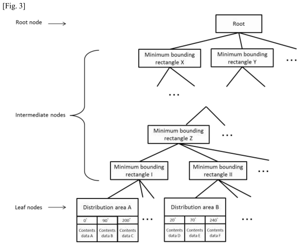
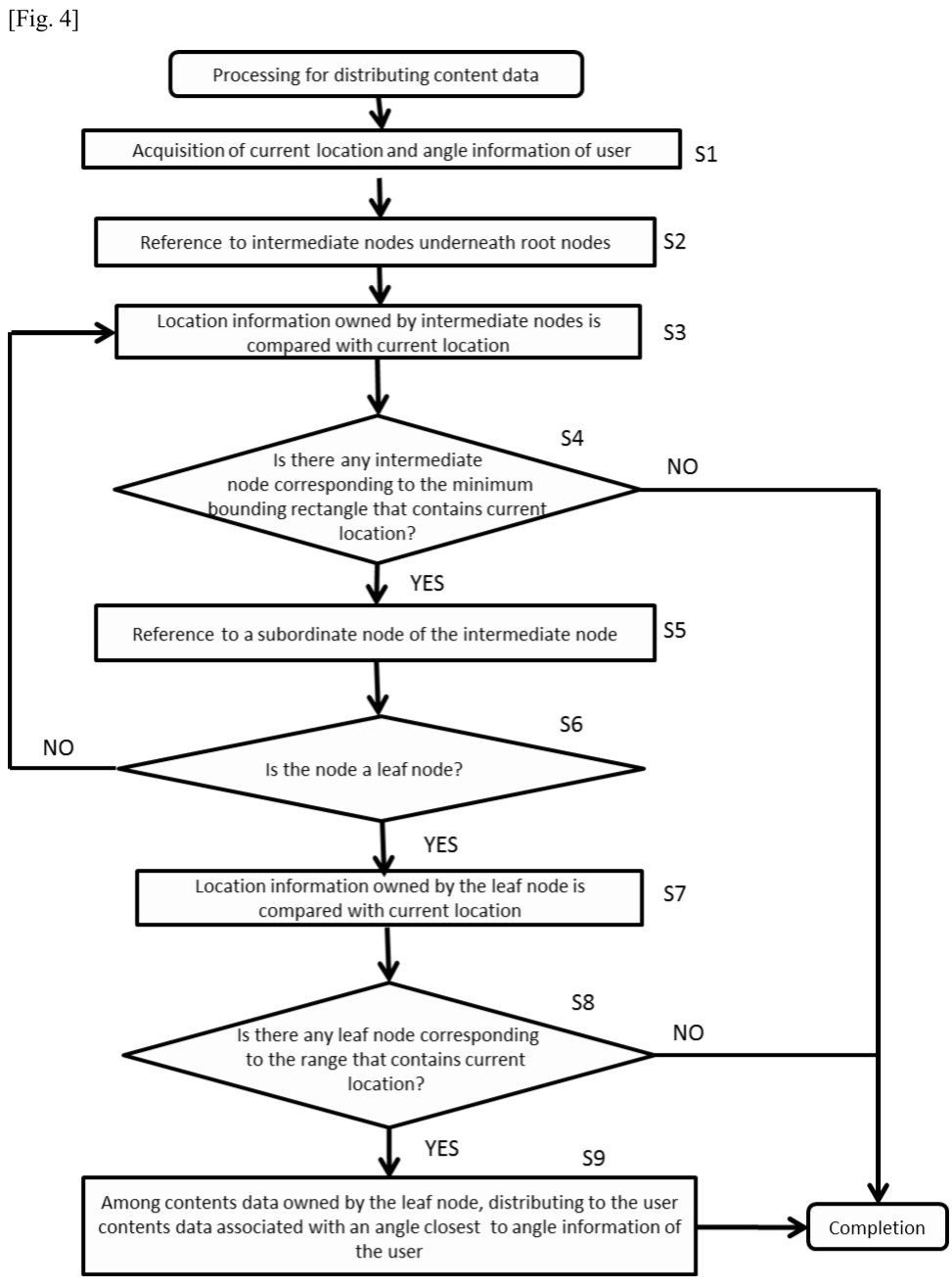
Overview of the description
[Technical Field] The present invention relates to a data structure for a technology to distribute contents data to users.
[Background Art] There is a service for users who own gaming machines that run on specific gaming applications within specific distribution areas on a map to distribute contents data on the game related to the distribution areas to their gaming machines. In this service, if a user is found to be in a specific distribution area while he/she is in transit, one contents data related to the distribution area is automatically distributed to his/her gaming machine. Moreover, it is envisaged that the user physically moves to a specific distribution area where he/she may receive contents data in order to acquire desired data. Furthermore, a method is known in which an enormous number of distribution areas for this service is managed by a tree-structure so that the present invention is designed in a way that processing for identifying distribution areas that geographically contain information on current positions of users is carried out only by comparing the number of stages of the tree structure.
[Problems to be solved by the invention] In order to further increase a game element of those applications, there is a method of distributing different contents data in accordance with angles to which users are facing even when they are in the same distribution area.
[Solution for the Problem to be solved] The present invention is characterized in that it associates a plurality of contents data by angles with one distribution area and holds such data. The present invention acquires from a gaming machine of a user, in addition to information on current location, angle information indicating a direction to which the gaming machine is facing as a search key. By this way, when the user (gaming machine) is determined to be in a specific distribution area, contents data on the basis of the angle information of the gaming machine is distributed.
[Description of the embodiments] As shown in the outline drawing of the present invention in Fig. 1, the contents distribution server acquires current location and angle information of users from their gaming machines as search keys, identifies distribution areas that geographically contain the current locations information, and distributes contents data associated with the angle among such data corresponding to the identified distribution areas to users. A gaming machine is equipped with the telecommunication function, current location acquisition function and a function to acquire an angle information to which the gaming machine is facing by the use of an angle sensor or by other means. An angle (0°~360°) is measured in the clockwise direction on the basis of due north as 0°. Contents data includes items and characters used on gaming applications that run on those gaming machines. The contents distribution server manages distribution areas and contents data in a way that they are included in the tree-structured area management data as described below and stored in a memory part the server is equipped with.
(Data structure of area management data)
Each distribution area defines location information based on information on latitude and longitude (x1, y1) (x2, y2) in the diagonal location of the rectangle. A distribution area is bounded by one minimum bounding rectangle together with two or more distribution areas nearby. The minimum bounding rectangle refers to a rectangle that bounds a plurality of distribution areas with the minimum area and defines location information based on information on latitude and longitude in the diagonal location of the rectangle in the same manner as distribution areas. A minimum bounding rectangle is bounded by a superordinate minimum bounding rectangle together with two or more minimum bounding rectangles nearby. By this way, a tree-structured data composed of a plurality of distribution areas and minimum bounding rectangles is formed.
A root node constitutes the uppermost location of data structure. A node corresponding to the minimum bounding rectangle is called intermediate node, while a node corresponding to a distribution area is called leaf node. A root node has pointers to a plurality of intermediate nodes underneath. Each of intermediate nodes has location information on a corresponding minimum bounding rectangle and pointers to a plurality of subordinate intermediate nodes or leaf nodes. Each of leaf nodes has location information on corresponding distribution area and a plurality of contents data associated with a plurality of angles.
Fig. 2 is an example of distribution areas and minimum bounding rectangles. The distribution areas A - C are bounded by the minimum bounding rectangle I, while the distributions areas D - F by the minimum bounding rectangle II.
Fig. 3 represents a structure of area management data formed in the case of Fig. 2. The intermediate nodes corresponding to the minimum bounding rectangle I have pointers to the leaf nodes corresponding to the distribution areas A - C, while that corresponding to the minimum bounding rectangle II has pointers to the leaf nodes corresponding to the distribution areas D - F. The uppermost root node has pointers to each of the intermediate nodes. Contents data in accordance with angle is associated with each of the leaf nodes.
(Processing for distributing contents data)
Fig. 4 is used to explain the processing for distributing contents data performed by the contents distribution server. Once the server acquires information on a current location and angle information of a user from his/her gaming machine as a search key (S1), it refers to the intermediate nodes underneath the root node (S2) and compares location information owned by the intermediate nodes with the information on current location (S3). Based on this comparison, it is determined whether or not there is any node corresponding to the minimum bounding rectangle that geographically contains the information on current location (S4), and if that is the case, subordinate nodes of the intermediate nodes are referred to (S5). If there is no such node, it is determined that there are no users in any of the distribution areas, and the processing completes and the processing for distributing contents data is not performed. Then, whether or not the subordinate nodes of the intermediate nodes are leaf nodes is determined (S6). If they are not leaf nodes, that is, if they are intermediate nodes, the process returns to S3 and the processing described in S3~S5 are repeated until those nodes reach a leaf node. If they are found to be leaf nodes, location information on distribution areas owned by the leaf nodes and the information on current location are compared (S7) to determine whether or not there is any leaf node corresponding to distribution areas that geographically contain the information on current location (S8). If that is the case, among a plurality of contents data associated with angles owned by the leaf node, contents data associated with an angle closest to angle information acquired from the user is distributed thereto (S9). On the other hand, if there is no corresponding leaf node, it is determined that there are no users in any of the distribution areas, and. the processing completes and the processing for distributing contents data is not performed.
Specific processing for distributing contents data is shown using the examples in Figs. 2 and 3. In these examples, a user exists in the distribution area C and is facing due south (180°). By repeating process of comparing location information on distribution areas owned by the root node and intermediate nodes with current location information, it is determined that current location information is contained geographically in the minimum bounding rectangle I. Then, location information on the distribution areas A - C owned by the subordinate leaf node underneath the intermediate nodes corresponding to the minimum bounding rectangle I is compared with information on current location to determine whether or not it is contained geographically in the distribution area C. Subsequently, among a plurality of contents data associated with angles owned by the leaf node corresponding to the distribution area C, contents data C associated with an angle (200°) closest to angle information acquired from the user (180°) is distributed thereto.
As discussed here, by distributing the contents data based on angle information of the gaming machine, it becomes possible to distribute different contents data depending on angles to which users are facing even if they are in the same area and thereby increase a game element.
- State of the art (Prior art, well-known art, etc.)
Cited invention 1 (Invention disclosed in the cited document 1 (D1)):
Tree-structured area management data comprising in the order of single-layer root node, multi-layer intermediate nodes and single-layer leaf nodes from top, wherein;
the said leaf nodes have location information on distribution areas and contents data;
among the said intermediate nodes, those equipped with the said plurality of leaf nodes underneath have pointers to the said plurality of leaf nodes underneath and location information having a minimum bounding rectangle that bounds the said plurality of distribution areas corresponding to the plurality of leaf nodes underneath with the minimum area;
among the said intermediate nodes, those equipped with a plurality of intermediate nodes underneath have pointers to the said plurality of intermediate nodes underneath and location information having the minimum bounding rectangle that bounds the said minimum bounding rectangles owned by the plurality of intermediate nodes underneath with the minimum area;
the said root node has pointers to the said plurality of intermediate nodes underneath;
wherein the tree-structured area management data is stored in a contents distribution server; and
it is used by the said contents distribution server to perform processing to identify leaf nodes corresponding to distribution areas that geographically bound current location information input as a search key in accordance with the pointers owned by root node or intermediate nodes.
(Problems to be solved)
To identify at high speed the only contents data corresponding to current location information by identifying at high speed distribution areas that geographically contain the said current location information of users input as a search key.

Cited invention 2 (Invention disclosed in the cited document 2 (D2)):
Data to which location information indicating a location on a map of a geographical area, angle information indicating an angle in which the said geographical area has a surface and sunlight information indicating the condition of sunlight in the geographical area by angles, wherein, the data is used, when a map of the said geographical area is displayed on a computer display, for processing to display it by associating the said sunlight information therewith by the said angle information.
(Problems to be solved)
When a geographical area is displayed on a map, sunlight information by angles relating to the geographical area is displayed.
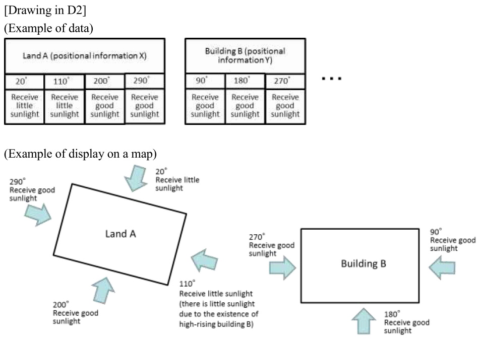
[Conclusion] The invention of Claim 1 involves an inventive step.
[Explanation]
(Considered motivation)
(1) Relation of technical fields
The cited invention 1 and the cited invention 2 have a common technical field in that both of them relate to a technology to manage information on geographical areas.
(2) Similarity of problems to be solved
The problem to be solved by the cited invention 1 is, by identifying at high speed a distribution area that geographically contains information on current location of a user input as a search key, to identify at high speed the only contents data corresponding to the said information on current location, while the problem to be solved by the cited invention 2 is, when a geographical area is displayed on a map, display specific information by angle with respect to the said geographical area. Therefore, the problems to be solved by the two inventions are not similar.
(3) Similarity of operations or functions
The cited invention 1 is tree-structured data and used for processing to, by identifying at high speed a distribution area that geographically contains information on current location of a user input as a search key, to identify at high speed the only contents data corresponding to the said information on current location, through information processing in accordance with pointers owned by the root nodes and intermediate nodes. On the other hand, the cited invention 2 is data with which a plurality of specific information is associated by angle of geographical areas and used for processing to display the plurality of information by angle by associating it with the geographical areas, and is not used for processing to identify information based on an input search key. Thus, the two invention are not common in terms of operations or functions.
(Explanation on the non-existence of an inventive step objection)
When the invention of Claim 1 and the cited invention 1 are compared, they are different in the following aspects.
(Difference)
The leaf node of area management data claimed in the invention of Claim 1 has a plurality of contents data by angle associated with location information on rectangular distribution areas and a plurality of angles and is used for processing to identify a leaf node corresponding to a distribution area that geographically contains information on current location input as a search key and to identify contents data associated with an angle closest to angle information input as a search key. On the other hand, the leaf node of area management data claimed in the cited invention 1 has location information of rectangular distribution areas and one contents data and is used only for processing to identify contents data associated with a leaf node corresponding to a distribution area that geographically contains information on current location input as a search key. However, it does not have contents data by angle nor it is used for processing to identify contents data associated with an angle closest to angle information input as a search key.
The above difference 1 is considered.
When considering the circumstances described from (1) to (3) above (considered motivation) comprehensively, it is not determined that there is a motivation of applying the cited invention 2 to the cited invention 1.
Moreover, an effect claimed in the invention of Claim 1 that the leaf node of area management data has a plurality of contents data by angle associated with plurality of angles so that different contents data may be distributed depending on angles to which users are facing even if they are in the same area is advantageous and not predicted based on the cited invention 1 or cited invention 2.
When taking the above circumstances into consideration comprehensively, it is not determined that a person skilled in the art could have easily arrived the invention of Claim 1.
[Case 3-5] 3D Printing Method and 3D Printing Data
Title of Invention
3D Printing Method and 3D Printing Data
What is claimed is:
[Claim 1] A 3D printing method that laminates model materials that finally constitute a 3D-modeled object, supporting materials that have the lattice shape in planar view and support the said model materials during modeling and intermediate materials that are made of the same materials as the said supporting materials and are located between the said model materials and the said supporting materials during modeling,
wherein the 3D printing method comprising in each of layers of the said 3D-modeled object:
a step of performing a modeling by dispensing the said model materials;
a step of performing a modeling by dispensing the said intermediate materials; and
a step of performing a modeling by dispensing the said supporting materials; and
wherein the 3D printing method carries out a step of,
(A) after the step of performing a modeling by dispensing the model materials, (A1) performing a modeling by dispensing the intermediate materials of the lowermost layer that have not been modeled at the time when the said step completed, in case where the model material of a next-higher layer has a protruding part in relation to the model material dispensed at the said step and where the intermediate material of the same layer has not been modeled at the time when the said step completed and (A2) performing a modeling by dispensing the model materials of the next-higher layer in case where it does not have a protruding part or where the intermediate material of the same layer has been modeled at the time when the said step completed,
(B) after the step of performing a modeling by dispensing the said intermediate materials, performing a modeling by dispensing the supporting materials of the layer in which the said step was carried out; and
(C) after the step of performing a modeling by dispensing the said supporting materials, (C1) performing a modeling by dispensing the model materials of the lowermost layer that have not been modeled at the time when the said step completed, in case where the supporting material and the intermediate material of a next-higher layer have protruding parts in relation to the supporting material and the intermediate material of the layer in which the step was carried out and where the model material of the same layer has not been modeled at the time when the said step completed and, (C2) performing a modeling by dispensing the intermediate materials of the next-higher layer in case where they do not have protruding parts or where the model material of the same layer in which the step was carried out has been modeled at the time when the said step completed.
[Claim 2] 3D printing data used in a 3D printer that laminates model materials that finally constitute a 3D-modeled object, supporting materials that have the lattice shape in planar view and support the said model materials during modeling and intermediate materials that are made of the same material as the said supporting materials and are located between the said model materials and the said supporting materials during modeling,
wherein the 3D printing data has a structure comprising in each of layers of the said 3D-modeled object:
model material data indicating the quantity and position of dispensation of the said model materials;
a model material pointer that points to data used for a modeling following a modeling based on the said model material data;
intermediate material data indicating the quantity and position of dispensation of the said intermediate materials;
an intermediate material pointer that points to data used for a modeling following a modeling based on the said model material data;
supporting material data indicating the quantity and position of dispensation of the said supporting materials;
a supporting material pointer that points to data used for a modeling following a modeling based on the said supporting material data;
wherein (A’) the said model material pointer is set, (A’1) to point to the intermediate material data of the lowermost layer that is not modeled at the time when modeling of the model material of the layer in which the modeling material pointer is included completed, in case where the model material of a next-higher layer has a protruding part in relation to the model material of the layer in which the model material pointer is included and where the intermediate material of the same layer has not been modeled at the time when the modeling of the model material of the layer in which the model material pointer is included completed and, (A’2) to point to the model material data of the next-higher layer, in case where it does not have any protruded part or an intermediate material of the same layer has been modeled at the time when the modeling completed,
wherein (B’) the said intermediate material pointer is set to point to supporting material data of the layer in which the pointer is included, and
wherein (C’) the said supporting material pointer is set, (C’1) to point to the model material data of the lowermost layer that is not modeled at the time when modeling of the supporting material of the layer in which the supporting material pointer is included completed, in case where the supporting material and the intermediate material of a next-higher layer have protruding parts in relation to the supporting material and the intermediate material of the layer in which the supporting material pointer is included and where the model material of the same layer has not been modeled at the time when the modeling of the supporting material of the layer in which the supporting material pointer is included completed and, (C’2) to point to the intermediate material data of the next-higher layer, in case where they do not have any protruding parts or the model material of the same layer has been modeled at the time when the modeling completed; and
wherein the 3D printing data is used by a control unit of the said 3D printer for processing to acquire the said model material data, the intermediate data or the supporting material data from its memory unit of the said 3D printer in accordance with the said model material pointer, intermediate material pointer or supporting material pointer after the modeling based on the said model material data, intermediate material data or supporting material data.
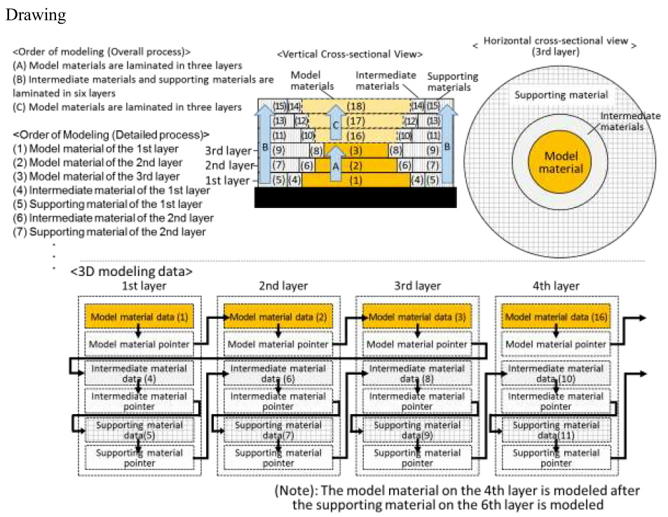
Overview of the description
[Background Art] A 3D printer models a 3D-modeled object by calculating data indicating a thinly-cut cross-sectional shape in the laminated direction and a position of dispensation corresponding to the cross-sectional shape based on data on three-dimensional shape of the 3D-modeled object, modeling each layer using model materials in accordance with the data and laminating each of the layers.
A 3D printer that laminates model materials that finally constitute a 3D-modeled object and supporting materials that support the said model materials is known. In case where an object to be modeled has a protruding part in relation to a lower-layer structure, the supporting materials are placed on the outer or inner circumference of the model materials to support the said protruding part of the model material until the modeling of 3D-modeled object completes and then removed once the modeling of 3D-modeled object completes.
Such a 3D printer is comprised of a dispensing unit that dispenses model materials and a dispensing unit that dispenses supporting materials separately and changes materials to be dispensed at every several layers with the aim of shortening the time of modeling by reducing the number of changes compared to the case where materials to be dispensed are changed at each layer. To be more specific, after the step of performing a modeling by dispensing model materials (or supporting materials), in case where model materials (or supporting materials) of next-higher layers in relation to the model materials (or supporting materials) have protruding parts and no supporting materials (or modeling materials) of the same layer have been modeled at the time when the step completed, a step of modeling lowermost layers by dispensing the supporting materials (or model materials) that have not been modeled at the time when the process completed is performed, and, in case where they do not have any protruding parts or supporting materials (or model materials) of the same layer have been modeled at the time when the process completed, 3D printing is performed by dispensing the model materials (or supporting materials) of the next-higher layers. By this way, model materials and supporting materials are laminated properly so that the number of changes of materials to be dispensed is reduced to the maximum extent possible.
[Problems to be solved by the invention] Since supporting materials support model materials during modeling and are removed once the modeling of a 3D-modeld object completes, they will be turned into waste after their use. It is preferable, therefore, to reduce the usage of supporting materials.
The present invention has been conceived in view of these circumstances and aims to provide 3D printing data capable of properly laminating model materials and supporting materials and reducing the number of changes of materials to be dispensed to the extent possible as well as reducing the usage of supporting materials that will be turned into waste and easily removing supporting materials.
[Solution for the Problem to be solved] The present invention is characterized in that it laminates, in addition to model materials, supporting materials that have the lattice shape in planar view and support the model materials during modeling and intermediate materials that are made of the same material as the supporting materials and are located between the model materials and supporting materials during modeling and specifies the order of modeling steps.
The present invention is, for example, embodied in an ink-jet 3D printer. A 3D printer is equipped with a control unit that sequentially acquires model material data, supporting material data or intermediate material data used for modeling among the 3D printing data from a memory unit in accordance with a pointer and that makes a dispensing unit to dispense materials. The 3D printer itself may be equipped with the memory unit or an external server connected to the 3D printer via a network may be equipped therewith
Since supporting materials of the present invention have the lattice shape in planar view, the quantity of such materials to be used is less than the case where they are applied evenly in one layer. Thus, the usage of supporting materials that are turned into waste is reduced. When supporting materials and intermediate materials are removed by dissolving them in solvents, it is easier for solvents to spread in the supporting materials and intermediate materials due to the lattice shape thereof. Moreover, since the quantity of supporting materials and intermediate materials to be dissolved is kept low, they can be dissolved and removed in a short period of time. Furthermore, a scanning movement of the dispensing unit at the time of modeling becomes linear due to the lattice shape of supporting materials allowing a modeling to be performed at high speed.
On the other hand, intermediate materials of the present invention are made of the same material as supporting materials and are located between model materials and the supporting materials. The intermediate materials have an interface in contact with the supporting materials and the interfaces finally become a surface of a 3D-modeled object after removing intermediate materials and supporting materials. Therefore, it is required to perform a modeling at good precision, but high precision is not required for the contacting surface between the supporting materials and the intermediate materials. Even if supporting materials have the lattice shape in planar view, it does not affect precision of the final 3D-modeled object. Moreover, since supporting materials and intermediate materials are made of the same material, after the step of performing a modeling by dispensing intermediate materials, a step of performing a modeling by dispensing supporting materials may be carried out of a layer in which the step for the intermediate materials was carried out as described later.
The 3D printing method of the present invention carries out a step of, (A) after the step of performing a modeling by dispensing the model materials, (A1) performing a modeling by dispensing the intermediate materials of the lowermost layer that have not been modeled at the time when the said step completed, in case where the model material of a next-higher layer has a protruding part in relation to the model material dispensed at the said step and where the intermediate material of the same layer has not been modeled at the time when the said step completed and (A2) performing a modeling by dispensing the model materials of the next-higher layer in case where it does not have a protruding part or where the intermediate material of the same layer has been modeled at the time when the said step completed, (B) after the step of performing a modeling by dispensing the said intermediate materials, performing a modeling by dispensing the supporting materials of the layer in which the said step was carried out; and (C) after the step of performing a modeling by dispensing the said supporting materials, (C1) performing a modeling by dispensing the model materials of the lowermost layer that have not been modeled at the time when the said step completed, in case where the supporting material and the intermediate material of a next-higher layer have protruding parts in relation to the supporting material and the intermediate material of the layer in which the step was carried out and where the model material of the same layer has not been modeled at the time when the said step completed and, (C2) performing a modeling by dispensing the intermediate materials of the next-higher layer in case where they do not have protruding parts or where the model material of the same layer in which the step was carried out has been modeled at the time when the said step completed. It should be noted that, even in case where the model materials or the supporting materials do not have any protruding part in relation to a lower layer, dispensed materials may be changed after laminating the predetermined number of layers, since a dispensing unit may collide with modeled layers when the dispensing unit comes close to the 3D-modeled object and modeling stage to dispense materials. Moreover, in case where supporting materials (or model materials) of all layers have not been modeled after the step of performing a modeling by dispensing model materials (or supporting materials) of the uppermost layer, the step of performing a modeling of supporting materials (or model materials) of the lowermost layer that has not been modeled at the time when the process completed is carried out.
The 3D printing data of the present invention is to realize the above 3D printing method and includes on each layer, together with model material data, intermediate material data and supporting material data, a pointer that points to data used for a modeling following a modeling based on such data. The model material data, intermediate model data and supporting material data here shall refer to data indicating materials (model materials, intermediate materials or supporting materials) to be dispensed from the dispensing unit of the 3D printer and the position and quantity of dispensation, respectively.
The pointer is now explained. (A’) The model material pointer is set, (A’1) to point to the intermediate material data of the lowermost layer that is not modeled at the time when modeling of the model material of the layer in which the modeling material pointer is included completed, in case where the model material of a next-higher layer has a protruding part in relation to the model material of the layer in which the model material pointer is included and where the intermediate material of the same layer has not been modeled at the time when the modeling of the model material of the layer in which the model material pointer is included completed and, (A’2) to point to the model material data of the next-higher layer, in case where it does not have any protruded part or an intermediate material of the same layer has been modeled at the time when the modeling completed. (B’) The intermediate material pointer is set to point to supporting material data of the layer in which the pointer is included. (C’) The supporting material pointer is set, (C’1) to point to the model material data of the lowermost layer that is not modeled at the time when modeling of the supporting material of the layer in which the supporting material pointer is included completed, in case where the supporting material and the intermediate material of a next-higher layer have protruding parts in relation to the supporting material and the intermediate material of the layer in which the supporting material pointer is included and where the model material of the same layer has not been modeled at the time when the modeling of the supporting material of the layer in which the supporting material pointer is included completed and, (C’2) to point to the intermediate material data of the next-higher layer, in case where they do not have any protruding parts or the model material of the same layer has been modeled at the time when the modeling completed. It should be noted that, even in cases where a model material or supporting material does not have any protruding part in relation to a next-lower layer, if dispensed materials are changed after laminating the predetermined number of layers, the pointer shall be set to realize such a change. Moreover, with regard to a model material pointer (or supporting material pointer), in case where supporting materials (or model materials) of all layers have not been modeled, it is set to point to the supporting material data (or model material data) of the lowermost layer that has not been molded at this moment, while, in cases where supporting materials (or model materials) of all layers have been modeled, it is set to point to the completion of modeling of all layers.
The case where an hour-glass shaped 3D-modeled object having six layers is explained using a pointer set in the above manner (It should be noted that it is rare that the lamination completes in six layers in actual 3D printing and hundreds or thousands of layers are usually laminated. The example gives an explanation supposing that the 3D-modeled object is composed of six layers in order to explain the idea of the present invention). When such a 3D-modeled object is modeled, it is required to place supporting materials and intermediate materials on the outer circumference of model materials. However, as model materials on the fourth to the sixth layers have protruding parts from their respective model materials on next-lower layers and supporting materials and intermediate materials on the first to the third layers have protruding parts from their respective next-lower layers, it is appropriate to laminate three layers of model materials, six layers of supporting materials and intermediate materials and then the remaining three layers of model materials. If there are a supporting material and an intermediate material in the same layer, the intermediate material is modeled first.
In this case, as for pointers in the 3D printing data, model material data of the second layer is pointed after the modeling based on model material data of the first layer, model material data of the third layer is pointed after the modeling based on model material data of the second layer, model material data of the first layer is pointed after the modeling based on model material data of the third layer, and supporting material data the first layer is pointed after the modeling based on the intermediate material data of the first layer (the same process is repeated for subsequent layers). Since a pointer may change data to be pointed by simple data editing, 3D printing data having such a structure with pointers may simply set the order of modeling, that is, the order of acquiring the data, after calculating data indicating a thinly-cut cross-sectional shape in the laminated direction and the quantity and position of dispensation of each material corresponding to the cross-sectional shape based on data of three-dimensional shape of the 3D-modeled object.
Since a control unit of a 3D printer sequentially acquires from a memory unit model material data, intermediate material data or supporting material data used for modeling among 3D printing data, such 3D printing data having a structure with pointers is preferable in cases where the size thereof is larger than the RAM capacity of the control unit of the 3D printer or the memory unit (and the conversion unit that converts data on 3D shapes of the 3D-modeled object into 3D printing data taking into account a cross-sectional shape of the 3D-modeled object and stores it in the said memory unit) is accommodated in an external server connected to the 3D printer over the network.
[Effect of Invention] The present invention is capable of properly laminating model materials and supporting materials and reducing the time of changes of materials to be dispensed to the extent possible as well as reducing the quantity of supporting materials used that are turned into wastes and removing supporting materials easily.
- State of the art (Prior art, well-known art, etc.)
Cited invention 1 (Invention disclosed in the cited document 1 (D1)):
A 3D printing method that laminates model materials that finally constitute a 3D-modeled object and supporting materials that support the said model materials during modeling,
wherein the 3D printing method comprising, in each of layers of the said 3D-modeled object:
a step of performing a modeling by dispensing the said model materials; and
a step of performing a modeling by dispensing the said supporting materials, and
wherein the 3D printing method carries out a step of,
(a) after the step of performing a modeling by dispensing the model materials, (a1) performing a modeling by dispensing supporting materials of the lowermost layer that have not been modeled at the time when the said step completed, in case where the model material of a next-higher layer has a protruding part in relation to the model materials dispensed at the said step and where the supporting material of the same layer has not been modeled at the time when the said step completed and (a2) performing a modeling by dispensing model materials of the next-higher layer, in case where it does not have protruding parts or where supporting material of the same layer has not been modeled at the time when the said step completed and
(c) after the said step of performing a modeling by dispensing the supporting materials, (c1) performing a modeling by dispensing model materials of the lowermost layer that have not been modeled at the time when the step completed, in case where the supporting material of a next-higher layer has a protruding part in relation to the supporting materials dispensed at the said step and where the model material of the same layer has not been modeled at the time when the said step completed and, (c2) performing a modeling by dispensing the supporting materials of the next-higher layer in case where it does not have protruding parts or where the model material of the same layer has been modeled at the time when the said step completed.
Moreover, the cited document 1 describes the following 3D printing data corresponding to the above 3D printing method.
3D printing data used in a 3D printer which laminates model materials that finally constitute a 3D-modeled object and supporting materials that support the said model materials during modeling,
wherein the 3D printing data has a structure comprising in each layer of the said 3D-modeled object:
model material data indicating the quantity and position of dispensation of the said model materials;
a model material pointer that points to data used for the following modeling of modeling based on the said model material data;
supporting material data indicating the quantity and position of dispensation of the said supporting materials; and
a supporting material pointer that points to data used for the following modeling of modeling based on the said supporting material data;
wherein (a) the model material pointer is set (a1) to point to the supporting material data of the lowermost layer that is not modeled at the time when modeling of the model material of the layer in which the modeling material pointer is included completed, in case where the model material of a next-higher layer has a protruding part in relation to the model material of the layer in which the model material pointer is included and where the supporting material of the same layer has not been modeled at the time when the modeling of the model material in which the model material pointer is included completed and, (a2) to point to the model material data of the next-higher layer, in case where the model material of the next-higher layer does not have the protruding part or where the supporting material of the same layer has been modeled at the time when the modeling completed, and
wherein (c’) the supporting material pointer is set (c’1) to point to the model material data of the lowermost layer that is not modeled at the time when modeling of the supporting material of the layer in which the supporting material pointer is included completed, in case where the supporting material of a next-higher layer has a protruding part in relation to the model material of the layer in which the supporting material pointer is included and where the model material of the same layer has not been modeled at the time when the modeling of the supporting material in which the supporting material pointer is included completed and, (c’2) to point to the supporting material data of the next-higher layer, in case where the supporting material of the next-higher layer does not have the protruding part or where the model material of the same layer has been modeled at the time when the modeling completed; and
wherein the 3D printing data is used by a control unit of the said 3D printer for processing to acquire the model material data or the supporting material data from a memory unit of the said 3D printer in accordance with the said model material pointer or the supporting material pointer after the modeling based on the said model material data or the supporting material data.
(Problems to be solved)
To reduce the number of changes of materials to be dispensed to the extent possible while properly laminating model materials and supporting materials.
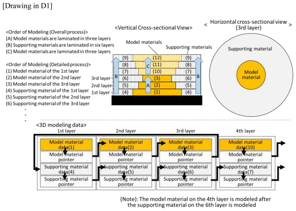
Cited invention 2 (Invention disclosed in the cited document 2 (D2)):
A 3D printing method to laminate model materials that finally constitute a 3D-modeled object, supporting materials that support the said modeling materials during modeling and intermediate materials that are different from the said supporting materials and made of materials whose releasability from the said model materials is high and that are located between the said model materials and the said supporting materials during modeling.
It should be noted that the cited document 2 does not describe the order of steps to perform modeling by dispensing the model materials, the supporting materials and the intermediate materials.
(Problems to be solved)
To easily and mechanically release and remove the supporting materials from the model materials without dissolving the supporting materials in solvents for removal
[Conclusion] The invention of Claim 1 involves an inventive step.
[Explanation]
(Considered motivation)
(1) Relation of technical fields
Both the cited invention 1 and the cited invention 2 relate to a 3D printing method to laminate model materials that finally constitute a 3D-modeled object and supporting materials that support the said model materials during modeling.
Therefore, they are common in technical fields to each other.
(2) Similarity of problems to be solved
Although the cited document 1 does not clearly describe a problem to be solved about the removal of supporting materials, making the removal of the supporting materials easier is an obvious problem for persons skilled in the art, because they are removed after the modeling of the 3D-modeled object completes.
Therefore, the cited document 1 and the cited document 2 are common in problems to be solved to each other.
(Explanation on the non-existence of an inventive step objection)
- Claim 1
When the invention of Claim 1 and the cited invention 1 are compared, they are different in the following points.
(Difference 1)
The invention of Claim 1 laminates materials including intermediate materials that are made of the same material as supporting materials and are located between model materials and supporting materials during modeling, and, relating to a step of performing modeling by dispensing the intermediate materials, carries out a step of, (A) after the step of performing a modeling by dispensing the model materials, (A1) performing a modeling by dispensing the intermediate materials of the lowermost layer that have not been modeled at the time when the said step completed, in case where the model material of a next-higher layer has a protruding part in relation to the model material dispensed at the said step and where the intermediate material of the same layer has not been modeled at the time when the said step completed, (B) after the step of performing a modeling by dispensing the said intermediate materials, performing a modeling by dispensing the supporting materials of the layer in which the said step was carried out; and (C) after the step of performing a modeling by dispensing the said supporting materials, (C2) performing a modeling by dispensing the intermediate materials of the next-higher layer in case where they do not have protruding parts or where the model material of the same layer in which the step was carried out has been modeled at the time when the said step completed. On the other hand, the cited invention 1 does not laminate materials including intermediate materials nor specify the steps of performing a modeling by dispensing the intermediate materials.
(Difference 2)
In the invention of Claim 1, the supporting materials have the lattice shape in planar view, while the cited invention 1 does not specify it.
The above difference 1 is considered.
Both the cited invention 1 and the cited invention 2 are common in technical fields to each other, because they relate to a 3D printing method to laminate model materials that finally constitute a 3D-modeled object and supporting materials that support the said model materials during modeling. Moreover, the cited document 1 does not clearly describe a problem about the removal of supporting materials, but making the removal of the supporting materials easier is an obvious problem for persons skilled in the art. Therefore, the cited document 1 and the cited document 2 are common in problem to be solved.
However, the cited invention 2 laminates materials including intermediate materials that are located between the model materials and the supporting materials, but the intermediate materials are not made of the same material as the supporting materials but of different types of materials. Moreover, the cited invention 2 does not specify the order of steps of performing a modeling by dispensing model materials support materials and intermediate materials.
Furthermore, the cited invention 2 makes it easier to mechanically release and remove the supporting materials from the model materials by using the intermediate materials that are different from the supporting material and whose releasability from the said model materials is high. Therefore, not only making it easier to remove supporting materials and intermediate materials by means of solvents by adopting the same material for those materials and but also reducing the number of changes of materials to be dispensed by setting a specific order of carrying out the step of performing a modeling by dispensing the intermediate materials, for example, by carrying out a step of performing a modeling by dispensing the supporting materials made of the same materials after the said step for the intermediate materials are not matters persons who had contact with the cited invention 1 and the cited invention 2 could have drawn from the common general technical knowledge.
The matter relating to the above difference 1 could not have been conceived only by applying the cited invention 2 to the cited invention 1 considering their technical fields and common problems and it cannot be deemed as a design variation (a design variation or adoption of a matter of design variation along with the specific application of an art to solve certain problem) that could have been made at the time of applying the cited invention 2 to the cited invention 1.
The above difference 2 is considered.
Although the cited invention 2 laminates materials including supporting materials, it does not specify that the supporting materials have the lattice shape in planar view.
Moreover, the cited invention 2 is to make it easier to mechanically release and remove supporting materials from model materials. Therefore, making it easier to remove supporting materials and intermediate materials by means of solvents by adopting the lattice shape in planar view for supporting materials is not a matter that persons skilled in the art who had contact with the cited invention 1 or the cited invention 2 could have drawn from the common general technical knowledge.
Thus, the matter relating to the above difference 2 could not have been conceived only by applying the cited invention 2 to the cited invention 1 and it cannot be deemed as a design variation (a design variation or adoption of a matter of design variation along with the specific application of an art to solve certain problem) that could have been made at the time of applying the cited invention 2 to the cited invention 1.
Moreover, based on the matters relating to the above differences 1 and 2, the invention of Claim 1 has an advantageous effect that cannot be predicted from the cited invention 1 or cited invention 2. That is, since the supporting materials have the lattice shape in planar view, solvents for dissolution and removal thereof can be spread easily. Moreover, as the intermediate materials are made of the same material as the supporting materials, they can be dissolved and removed at one time in a short period of time. After a step of performing modeling by dispensing the intermediate materials, a step of performing a modeling is carried out by dispensing the supporting materials made of the same material, it is not necessary to change materials to be dispensed. Moreover, even if the supporting materials has the lattice shape in planar view, they do not affect the precision of the final 3D-modeled object.
When considering these circumstances comprehensively, persons skilled in the art could not have easily conceived of the invention of Claim 1.
- Claim 2
The 3D printing data in the invention of Claim 2 realizes the 3D printing method in the invention of Claim 1.
Therefore, for the same reason as the invention of Claim 1, persons skilled in the art could not have easily conceived of the invention of Claim 2.